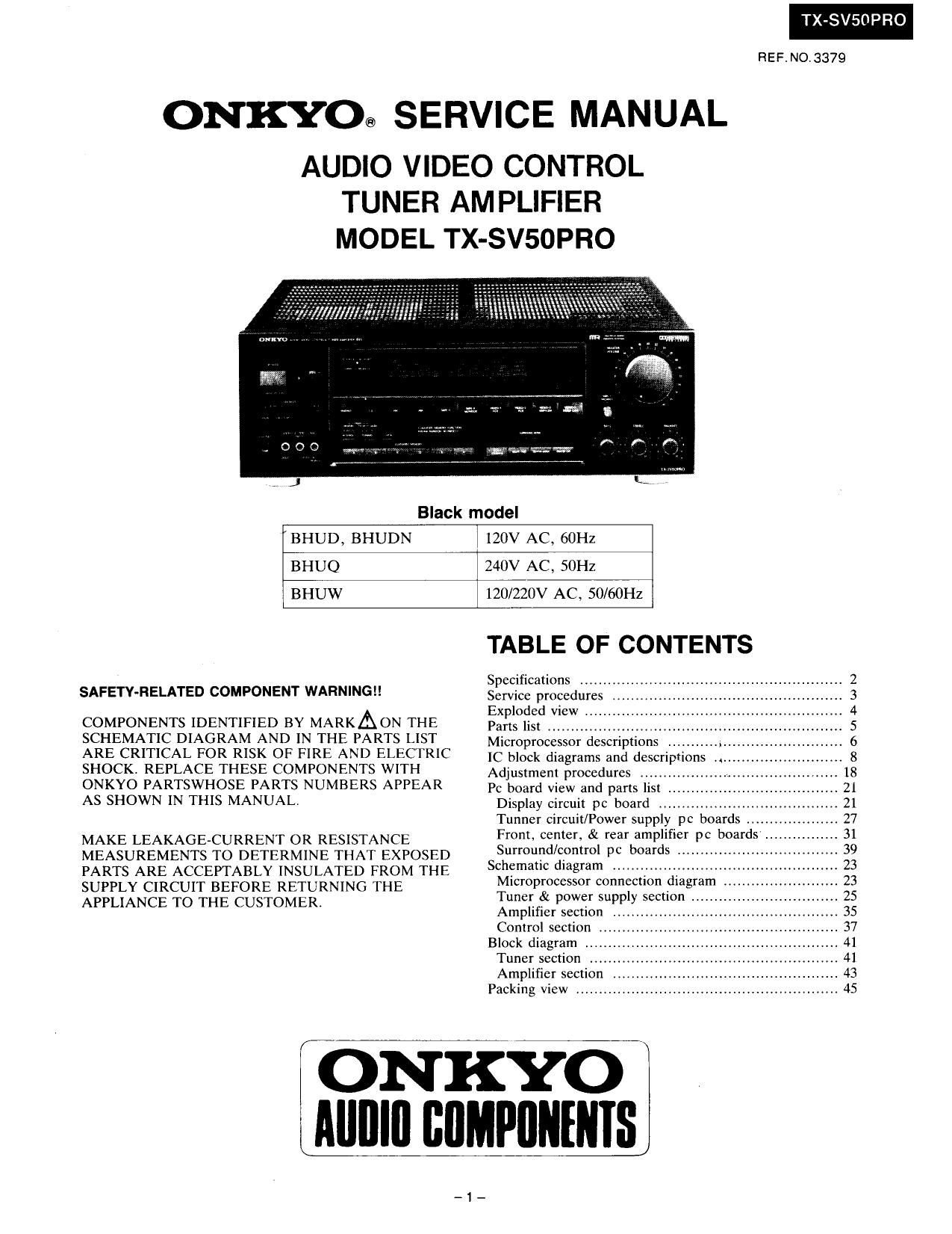
Onkyo TXSV 50 PRO Service Manual

This is the 29 pages manual for Onkyo TXSV 50 PRO Service Manual.
Read or download the pdf for free. If you want to contribute, please mail your pdfs to info@audioservicemanuals.com.

Page: 1 / 29
left right
Onkyo TXSV 50 PRO Service Manual

Extracted text from Onkyo TXSV 50 PRO Service Manual (Ocr-read)


Page 1

TX-SV5DPRO

REF.NO.3379

ONKYO@ SERVICE MANUAL

AUDIO VIDEO CONTROL
TUNER AMPLIFIER
MODEL TX-SV50PRO

Black model

BHUD, BHUDN

120V AC, 601-12

BHUQ

240V AC, SOHZ

BHUW

120/220V AC , 50/60Hz

SAFETY-RELATED COMPONENT WARNINGII

COMPONENTS IDENTIFIED BY MARKAON THE
SCHEMATIC DIAGRAM AND IN THE PARTS LIST
ARE CRITICAL FOR RISK OF FIRE AND ELECTRIC
SHOCK, REPLACE THESE COMPONENTS WITH
ONKYO PARTSWHOSE PARTS NUMBERS APPEAR
AS SHOWN IN THIS MANUAL.

MAKE LEAKAGECURRENT OR RESISTANCE
MEASUREMENTS TO DETERMINE THAT EXPOSED
PARTS ARE ACCEPTABLY INSULATED FROM THE
SUPPLY CIRCUIT BEFORE RETURNING THE
APPLIANCE TO THE CUSTOMER.

TABLE OF CONTENTS

Specifications .........
Service procedures
Exploded View .l
Parts list ..........
Microprocessor descriptions ........... .,..
lC block diagrams and descriptions .i
Adjustment procedures
Pc board View and parts list .
Display circuit pc board
Tunncr circuit/Power supply pc boards ......
Front, center, & rear amplifier pc boards
Surround/control pc boards .
Schematic diagram ...............
Microprocessor connection diagram
Tuner & power supply section
Amplifier section .
Control section ..
Block diagram ,,
Tuner section .
Amplifier section ,
Packing view ............


ONKYO
Alllllll IIIIMPIIIIIIIISJ

-1_

Page 3

SERVICE PROCEDURES

1. Replacing the fuses

For continued protection against fire hazard, replace only
with same type and same rating fuse.

D (120V) model

Circuit No. Part No. Description
F901 252051 6A (ST-6), Primary
F903,F904 252051 6A (ST-6), Secondary

Q (240V) model

Circuit No. Part No. Description
F902 252076 3.15A-SE-EAK, Primary
F903, F904 252078 SA-SE-EAK, Secondary

W (Worldwide) model

Circuit No. Part No. Description

F901 252051 6A (ST -6), Primary
F902 252076 3.15A-SE-EAK, Primary
F903,F904 252078 SA-SE-EAK, Secondary

2. Change of AM band selector
With the exception of the worldwide model. 21 AM BAND
step selector switch is not provided.

Band step D716 (185133)
lOkHz-> 9kHz Additional
9kHz -> 10kHz Eliminated

The diode D716 is on the display pc board. (Refer to the
page 21)

- Worldwide model -

Woldwide models are equipped with a band step selector
switch. This switch is located on the back panel. This switch
is set to 9kHz at the factory. but may have to be reset to

10kHz depending on the area where the unit is used.

Band step
U.SiA. IOkHz
Other region 9kHz

3. Memory preservation

This unit does not require memory preservation batteries.
A built-in memory power back-up system preserves
contents of the memory during power failures and even
when the unit is unplugged. The unit must be plugged in
and the power switch turned on and off once in order to
charge the back-up system. Note that since this is not a
permanent memory the power switch must be turned on
and off a few times each month to keep the back-up
system operative. The period of time during which
memory contents are preserved after power has last been
turned off varies depending on climate and placement of
the unit. On the average, memory contents are protected
over a period of 3 to 4 weeks (a minimum of2 weeks) after
the last time power has been turned off. This period is
shorter when the unit is exposed to very high humidity or
used in an area with an extremely humid climate.

TX-SVSOPRO

r-fi
FQOI
A
D EEC] A
7902

._4
Power supply circuit pc board

E

90

EBEED

1
A
u

Tuner circuit pc board

4. Safety-check out
(Only U.S.A. model)
After correcting the original service problem perform

'the following safety check before releasing the set to the

customer.

Connect the insulating-resistance tester between the plug of
power supply cord and terminal GND on the back panel.
Specifications: 3.3 Mohm 110% at 500V.

5. Change of voltage

Worldwide models are equipped with a voltage selector to
conform with local power supplies. This switch is located
on the back panel. Be sure to set this switch to match the
voltage of the power supply in your area before turning the
power switch on.

This switch is set to 220V at the factory. Voltage is
changed by sliding the groove in the switch with the screw-
driver to the right or left. Confirm that the switch has been
moved all the way to the right or left before turning the
power switch on.

Page 29

TX-SVSOPRO

PACKING VIEW

REF.NO.

\JfimwaH

transmitter

PART NO.
29052104
29091422A
29091423A
29100035A
282301

29] 10071-1
Accessary bag
29341556A
29100097
26206413
232140
3010054
24140186

2010200
29365019
29358002]
25060123
25055018

DESCRIPTION

Master carton box

Pad L

Pad R

1020X720, Poly-styrene bag
Sealing hook

Damplon tape

assy

Instruction manual

250x350, Polystyrene bag
FM antenna

NMA»3057, AM loop antenna
UM-3, Two batteries
RC-AV50M. Remote control

Remote control cord

Warranty card [D]

Service station list [D]
YAE21~0120A, FM adaptor [W/Q]
CV-K-l, Conversion plug [W]

[D]: Only U,S.A. models
[W]: Only Worldwide models
[0]: Only 240V models

ONKYO CORPORATION

International Divlslon: Onarimon Vusen Bldg. 23-5, Nishi-Shimbashi 3-chome. Minalo-ku.
TOKYO 105. JAPAN Telex: 242-3551 ONKYO J. Tel. 013-432-6981

ONKYO U.S.A CORPORATION

200 Wllllams Drive. Ramsey, N.J. 07446 Telex: 25-710-988-1033 Tel. 201-525-7950

A009 Printed in Japan

-46-