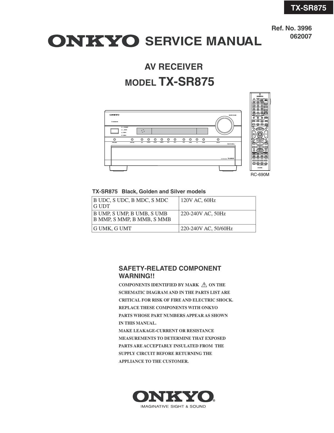
Onkyo TXSR 875 Service Manual

This is the 269 pages manual for Onkyo TXSR 875 Service Manual.
Read or download the pdf for free. If you want to contribute, please mail your pdfs to info@audioservicemanuals.com.

Page: 1 / 269
left right
Onkyo TXSR 875 Service Manual

Extracted text from Onkyo TXSR 875 Service Manual (Ocr-read)


Page 1

ON KYO SERVICE MANUAL

AV RECEIVER
MODEL TX-SR875

910 ald'q'qo a a
olo Noah

III
m
a
Eh

g

l
I

H
I E
[l
I!

m?
b,

TX-SR875 Black, Golden and Silver models

In
0
m
(o
o
E

B UDC, S UDC, B MDC, S MDC
G UDT

120V AC, 60Hz

B UMP, S UMP, B UMB, S UMB
B MMP, S MMP, B MMB, S MMB

220-240V AC, SOHZ

G UMK, G UMT

220-240V AC, 50/60Hz

SAFETY-RELATED COMPONENT
WARNING! !

COMPONENTS IDENTIFIED BY MARK A ON THE
SCHEMATIC DIAGRAM AND IN THE PARTS LIST ARE

CRITICAL FOR RISK OF FIRE AND ELECTRIC SHOCK.

REPLACE THESE COMPONENTS WITH ONKYO
PARTS WHOSE PART NUMBERS APPEAR AS SHOWN
IN THIS MANUAL.

MAKE LEAKAGE-CURRENT OR RESISTANCE
MEASUREMENTS TO DETERMINE THAT EXPOSED
PARTS ARE ACCEPTABLY INSULATED FROM THE
SUPPLY CIRCUIT BEFORE RETURNING THE
APPLIANCE TO THE CUSTOMER.

ONKYO®

IMAGINATIVE SIGHT SI SOUND

-SR875

Ref. No. 3996
062007

Page 68

IC BLOCK DIAGRAMS AND TERMINAL DESCRIPTIONS -14
03701,03721,03741,Q3761,Q3781: PCM1796DBR (24 bit, 192 kHz, 20h DAC)

TERMINAL DESCRIPTION

TERMINAL

NAME PIN llO DESCRIPTIONS
AGND1 19 - Analog ground (internal bias)
AGND2 24 - Analog ground (internal bias)
AGNDSL 27 - Analog ground (L-channel DACFF)
AGND3R 16 - Analog ground (R-channel DACFF)
BCK 6 l Bit clock input( 1)
DATA 5 I Serial audio data inputfl)
DGND 8 - Digital ground
lQUTL+ 25 O L-channel analog current output+
IOUTL- 26 O L-channel analog current output-
IQUTR+ 17 O R-channel analog current output+
IOUTR- 18 O R-channel analog current output-
IREF 20 - Output current reference bias pin
LFiCK 4 | Left and right clock (t3) inpuiU)
MC 12 | Mode control clock input)
MDI 11 | Mode control data input)
MDO 13 VD Mode control readback data outputi3)
W 10 VD Mode control chip-select input(2)
MSEL 3 | iZC/fi select)
R-ST 14 | Reset)
SCK 7 | System clock input)
V001 23 - Analog power supply, 5 V
VCC2L 28 - Analog power supply (L-channel DACFF), 5 V
V0029 15 - Analog power supply (Ft-channel DACFF), 5 V
VCOML 22 - L-channel internal bias decoupling pin
VCOMR 21 - R-channel internal bias decoupling pin
VDD 9 - Digital power supply, 3.3 V
ZEROL 1 |/O Zero flag for L-channei(2)
ZEROR 2 I/O Zero flag for R-ehannei(2)

(1) Schmitt-trigger input, 5-V tolerant

(2) Schmitt-trigger input and output. 5-V tolerant input and CMOS output

(3) Schmitt-trigger input and output. 5-V tolerant input. In I20 mode, this pin becomes an open-drain 3-state output; otherwise, this pin is a CMOS
output.

Page 84

IC BLOCK DIAGRAMS AND TERMINAL DESCRIPTIONS -30
03601 : D707E001BRFP250 (32 bit Floating-Point Digital Signal Processor)

TERMINAL DESCRIPTION(2/3)

SIGNAL NAME PIN NO. TYPE DESCRIPTION

McASPO, McASP1, McASP2, and SPI1 Serial Ports
AHCLKRO/AHCLKR1 143 IO McASPO and McASP1 Receive Master Clock
ACLKRO 139 I0 McASPO Receive Bit Clock
AFSRO 141 I0 McASPO Receive Frame Sync (L/R Clock)
AHCLKXO/AHCLKX2 2 IO McASPO and McASP2 Transmit Master Clock
ACLKXO 142 I0 McASPO Transmit Bit Clock
AFSXO 144 IO McASPO Transmit Frame Sync (L/R Clock)
AMUTEO 3 O McASPO MUTE Output
AXRO[0] 113 I0 McASPO Serial Data 0
AXRO[1] 115 I0 McASPO Serial Data 1
AXRO[2] 116 IO McASPO Serial Data 2
AXRO[3] 117 IO McASPO Serial Data 3
AXRO[4] 119 I0 McASPO Serial Data 4
AXRO[5]/m 120 IO McASPO Serial Data 5 or SP|1 Slave Chip Select
AXRO[6]/m 121 I0 McASPO Serial Data 6 or SP|1 Enable (Ready)
AXR0[7]/SPI17CLK 122 I0 McASPO Serial Data 7 or SP|1 Serial Clock
AXRO[8]/AXR1[5]/ 126 l0 McASPO Serial Data 8 or McASP1 Serial Data 5 or
SPILSOMI SP|1 Data Pin Slave Out Master In
AXRO[9]/AXR1[4]/ 127 IO McASPO Serial Data 9 or McASP1 Serial Data 4 or
SPILSIMO SP|1 Data Pm Slave In Master Out
AXRO[10]/AXR1[3] 130 I0 McASPO Serial Data 10 or McASP1 Serial Data 3
AXRO[11]/AXR1[2] 131 IO McASPO Serial Data 11 or McASP1 Serial Data 2
AXRO[12]/AXR1[1] 134 I0 McASPO Serial Data 12 or McASP1 Serial Data 1
AXRO[13]/AXR1[O] 135 IO McASPO Serial Data 13 or McASP1 Serial Data 0
AXRO[14]/AXR2[1] 137 IO McASPO Serial Data 14 or McASP2 Serial Data 1
AXRO[15]/AXR2[O] 138 I0 McASPO Serial Data 15 or McASP2 Serial Data 0
ACLKR1 9 IO McASP1 Receive Bit Clock
AFSR1 12 IO McASP1 Receive Frame Sync (L/R Clock)
AHCLKX1 5 IO McASP1 Transmit Master Clock
ACLKX1 IO McASP1 Transmit Bit Clock
AFSX1 11 IO McASP1 Transmit Frame Sync (L/R Clock)
AMUTE1 4 O McASP1 MUTE Output

SPIO, IZCO, and l2C1 Serial Port Pins
SPIO,SOM|/IZCO,SDA 111 I0 SPIO Data Pin Slave Out Master In or |2C0 Serial Data
SPIO,S|MO 110 I0 SPIO Data Pin Slave ln Master Out
SPIO,CLK/I2CO,SCL 108 I0 SPIO Serial Clock 0r |2CO Serial Clock
WMCLSCL 107 I0 SPIO Slave Chip Selector I201 Serial Clock
W/QCLSDA 105 I0 SPIO Enable (Ready) or |2C1 Serial Data

Page 98

IC BLOCK DIAGRAMS AND TERMINAL DESCRIPTIONS -44
03461, 03471, 03561: IC42$16100 (16-Mbit Synchronous Dynamic RAM)

TERMINAL DESCRIPTION

Pin No. Pin name Function (In Detail)
20 to 24 A0»A10 A0 toA10 are address inputs. A0»A10 are used as row address inputs during active command input
27 to 32 and A0-A7 as column address inputs during read or write command input. A10 is also used to
determine the precharge mode during other commands If A10 is LOW during precharge command,
the bank selected by All is precharged, but if A10 is HIGH, both banks will be precharged.
When A10 is HIGH in read or write command cycle, the precharge starts automatically after
the burst access.
These signals become part of the OP CODE during mode register set command input
19 A11 A11 is the bank selection signal. When All is LOW, bank 0 is selected and when high, bank 1 is
selected, This signal becomes part of the OP CODE during mode register set command input
16 m m in conjunction with the m and W, forms the device command See the "Command Truth
Table" item for details on device commands.
34 CKE The CKE input determines whether the CLK input is enabled within the device
When is CKE HIGH, the next rising edge of the CLK signal will be valid, and when LOW, invalidi
When CKE is LOW, the device will be in either the power-down mode, the clock suspend mode,
or the self refresh model The CKE is an asynchronous input
35 CLK CLK is the master clock input for this device Except for CKE, all inputs to this device are acquired
in synchronization with the rising edge of this pin
18 K The é input determines whetherflmmand input is enabled wit@ the device.
Command input is enableidwhen CS is LOW, and disabled with CS is HIGH The device remains in
the previous state when CS is HIGH.
2, 3, 5, 6, 8, 9, 1/00 1/00 to I/OIS are 1/0 pins. I/O through these pins can be controlled in byte units using the LDQM and
11, 12, 39, 40, to UDQM pins.
42, 43, 45, 46, 1/015
48, 49
14, 36 LDQM, LDQM and UDQM control the lower and upper bytes of the 1/0 buffers. In read mode, LDQM and
UDQM UDQM control the output buffer. When LDQM or UDQM is LOW,
the corresponding buffer byte is enabled, and when HIGH, disabled. The outputs go to theHIGH
impedance state when LDQM/UDQM is HIGH This function corresponds to E in conventional
DRAMs. In write mode, LDQM and UDQM control the input bufferi
When LDQM or UDQM is LOW, the corresponding buffer byte is enabled, and data can be written to
the device. When LDQM or UDQM is HIGH, input data is masked and cannot be written to the device.
17 RAS RAS, in conjunction with CAS and W, forms the device command See the Command Truth
Table" item for details on device commands.
15 W W, in conjunction with RAS and CAS, forms the device command. See the "Command Truth
Table" item for details on device commands.
7, 13, 38, 44 VCCQ VCCQ is the output buffer power supply.
1, 25 VCC VCC is the device internal power supply.
4, 10, 41, 47 GNDQ GNDQ is the output buffer ground.
26, 50 GND GND is the device internal ground.

Page 107

IC BLOCK DI AGRAMS AND TERMINAL DESCRIPTIONS -53
08800: ADV7401 (Multi-Format SDTV/HDTV Video Decoder)

TERMINAL DESCRIPTION (2/3)

Pin No. Mnemonic Type Function

33, 32, 31, P22-P29 1/0 Video input/output port

30, 29, 24,

14, 13

44, 43, 21, P04P1, P1(L I Video pixel input port.

20, 45, 34, P11, P207P21,

2, 1, 100, P317P4O

97, 96, 95,

88, 87, 84,

83

3 INT 0 Interrupt pin, can be active low or active high. When SDP/CP
status bits change this pin will trigger. The set of events which
will trigger an interrupt are under user control.

4 HS/CS 0 HS is a horizontal synchronization output signal in SDP and
CP modes. CS is a digital composite synchronization signal
that can be selected while in CF mode.

99 VS 0 VS is a vertical synchronization output signal in SDP and CP
modes.

98 FIELD/DE O FIELD is a field synchronization output signal in all
interlaced video modes. This pin also can be enabled as a DE
(Data Enable) signal in CF mode to allow direct connection to
a HDMI/DVI Tx IC.

81, 19 SDAl, SDA2 l/O 12C port serial data inpquutput pin, SDAl is the data line for
the Control port and SDA2 is the data line for the VBI
readback port.

82, 16 SCLKl, I 2C port serial clock input (max clock rate of 400 kHz).

SCLK2 SCLKl is the clock line for the Control port and SCLK2 is
the clock line for the VBI data readback port.

80 ALSB I This pin selects the 12C address for the ADV7401 Control and
VBI readback ports. ALSB set to a logic 0 sets the address for
a write to control port of 0x40 and the readback address for
the VBI port of 0x21. ALSB set to a logic high sets the
address for a write to control port of 0x42 and the readback
address for the VBI port of 0x23.

78 RESET 1 System reset input, active low. A minimum low reset pulse
width of 5 ms is required to reset the ADV7401 circuitry.

36 LLCl O LLCl is a line locked output clock for the pixel data (range is
12.825MHz to 140MHz for ADV7401KSTZ-140;
12.825MHz to 110MHz for ADV7401BSTZ-110;
12.825MHz to 80MHz for ADV7401BSTZ-80).

38 XTAL I Input pin for 2863636 MHz crystal, or can be overdriven by
an external 3.3 V 28.63636 MHz clock oscillator source to
clock the ADV7401.

37 XTALl O This pin should be connected to the 28.63636 MHz crystal or
left as a no connect if an external 3.3 V 28.63636 MHz clock
oscillator source is used to clock the ADV7401. In crystal
mode the crystal must be a fundamental crystal.

46 ELPF O The recommend external loop filter must be connected to this
ELPF pin.

70 TESTO These pins should be left unconnected or alternatively tie to
AGN D

59 TESTl 0 These pins should be left unconnected