Onkyo TXSR 504 E Service Manual

This is the 136 pages manual for Onkyo TXSR 504 E Service Manual.
Read or download the pdf for free. If you want to contribute, please mail your pdfs to info@audioservicemanuals.com.

Page: 1 / 136
left right
Onkyo TXSR 504 E Service Manual

Extracted text from Onkyo TXSR 504 E Service Manual (Ocr-read)


Page 1

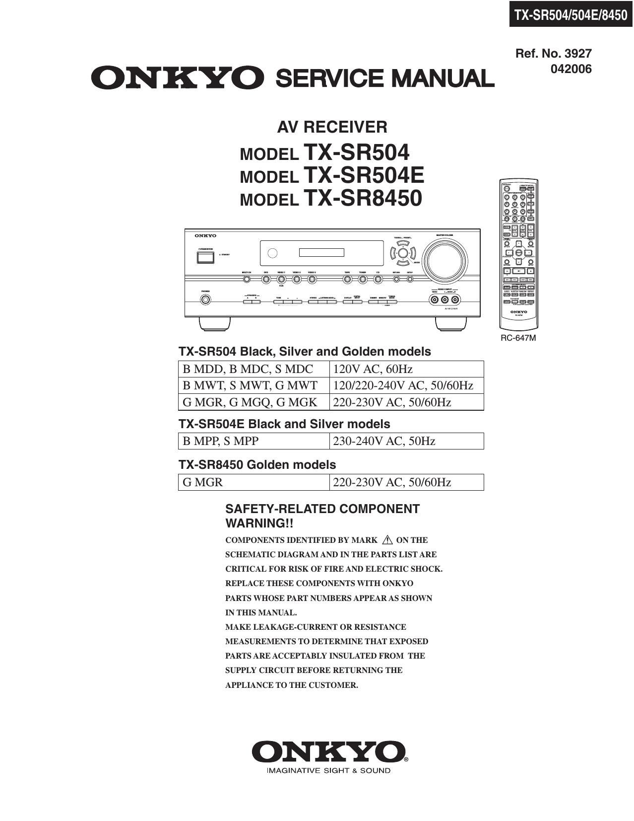
TX-SR504/504E/8450

Ref. No. 3927

ONKYO SERVICE MANUAL 2"

AV RECEIVER

MODEL TX-S R504
MODEL TX-SR504E
MODEL TX-S R8450

omo _ m

I?
Em A

:Qfi # H16>:<5F@-@ o o

s0!

IE}

TX-SR504 Black, Silver and Golden models

B MDD, B MDC, S MDC 120V AC, 60Hz

B MWT, S MWT, G MWT 120/220-240V AC, 50/60Hz
G MGR, G MGQ, G MGK 220-230V AC, 50/60Hz

TX-SR504E Black and Silver models
I B MPP, s MPP l230-240V AC, 50Hz I

TX-SR8450 Golden models
I G MGR l220-230V AC, 50/60Hz I

FIG-647M

SAFETY-RELATED COMPONENT
WA R N I N G I I

COMPONENTS IDENTIFIED BY MARK A ON THE
SCHEMATIC DIAGRAM AND IN THE PARTS LIST ARE
CRITICAL FOR RISK OF FIRE AND ELECTRIC SHOCK.
REPLACE THESE COMPONENTS WITH ONKYO
PARTS WHOSE PART NUMBERS APPEAR AS SHOWN
IN THIS MANUAL.

MAKE LEAKAGE-CURRENT 0R RESISTANCE
MEASUREMENTS TO DETERMINE THAT EXPOSED
PARTS ARE ACCEPTABLY INSULATED FROM THE
SUPPLY CIRCUIT BEFORE RETURNING THE
APPLIANCE To THE CUSTOMER.

ONKYO®

IMAGINATIVE SIGHT SI SOUND

Page 2

SERVICE PROCEDURE

1. Replacing the fuses

EE This symbol located near the fuse indicates that the
fuse used is show operating type, For continued protection against

fire hazard, replace with same type fuse, For fuse rating, refer to
the marking adjacent to the symbol.

EE Ce symbole indique que le fusible utilise est e lent.

Pour une protection permanente, n'utiliser que des fusibles de meme
type. Ce demier est indique la qu le present symbol est apposre.

REF NO. PART NAME DESCRIPTION PART NO. REMARKS

F901 FUSE 8A-UL/T-233 252329GR l,

F901 or FUSE 8A-T/UL-ST2 252261GR l,

F901 FUSE 4A-SE-EAK 252077GR l,

F901 or FUSE 4A-SE-TL250V 252277GR l,

F901 FUSE 4A-SE-EAK 252077GR l, , <8450>
F901 or FUSE 4A-SE-TL250V 252277GR l, , <8450>
F901 FUSE 4A-SE-EAK 252077GR l,

F901 or FUSE 4A-SE-TL250V 252277GR l,

F902 FUSE 4A-SE-EAK 252077GR l,

F902 or FUSE 4A-SE-TL250V 252277GR l,

F903 FUSE 5A-UL/T-233 252326GR l,

F903 or FUSE 5A-T/UL»ST2 252258GR l,

F903 FUSE 2,5A-SE-EAK 252075GR l,

F903 or FUSE 2,5A-SE-TL250V 25227SGR l,

F903 FUSE 2,5A»SE-EAK 25207SGR l, , <8450>
F903 or FUSE 2.5A-SE-TL250V 252275GR l, , <8450>
F6901 FUSE lOA-UL/T-233 25233OGR l

F6901 or FUSE lOA-T/UL-ST2 25233SGR l

F6902 FUSE lOA-UL/T-233 252330GR l

F6902 or FUSE lOA-T/UL-ST2 252333GR l

: TX»SR504 USA model
: TX»SR504 Canadian model
: TX-SR504E European model
: TX-SR504 World wide model

2.To initialize the unit

1. Press and hold down VIDEO 1NCR button, then press STANDBY/ON button when the unit is powered on.
2, After " Clear " is displayed, the preset memory and each mode stored in the memory, are initialized and
will return to the factory settings.

3. To check version of microprocessor

Main microprocessor Q701 only.

: TX-SR504 Chinese model only
: TX-SR504 Hong kong model only
: TX-SR504 Korean model only
<8450> : TX-SR8450 Chinese model only

1. Press and hold down DISPLAY button, then press STANDBY/ON button when the unit is powered on.
The version will be displayed on FL display only for 3 seconds.

Ex.

Ver.1.01/05305-

2, Press STANDBY/ON button to power off.

4. Memory Backup
The AV receiver uses a battery-less memory backup system in order to retain radio presets and other settings
when it's unplugged or in the case of a power failure.
Although no batteries are required, the AV receiver must be plugged into an AC outlet in order to charge the
backup system. Once it has been charged, the AV receiver will retain the settings for several weeks,
although this depends on the environment and will be shorter in humid climates.

Page 68

IC BLOCK DIAGRAMS AND TERMINAL DESCRIPTIONS-13
0301 : CS42518 (8-ch Codec with S/PDIF Receiver)-2/4

PIN CONFIGURATION

N n v I- 5
z z 3 g 5 N 8 g
o o a r: E z D
wlw1m1flj§55w1§flmg 118
>( X X D D X X
0 L) O a g 0 < < O D: a 5 D 2 fi CE
I_II_II_II_II_II_II_II_II_II_II_II_II_II_II_II_I
V ('J N - O 0) w B L0 ln V 0') N - O U)
{D (D (O (D {D In LG I!) In ln ln In In La In V
CX,SD|N1 E1 48]RXP1/GP01
CXESCLK E 2 47 ] RXP1/GPO1
CXELFICK E a 46 ] RXP1/GP01
VD [4 45 ] RXP1/GP01
DGND E5 44 ] RXP1/GP01
VLC E e 43 ] RXP1/GP01
SCL/CCLK E 7 42 ] RXP1/GP01
SDA/CDOUT E a CS42518 41 :IVARX
AD1/CDIN E9 40 ] AGND
ADO/CS E 10 39 ] LPFLT
INT E 11 38 ] MUTEC
FIST E 12 37 ] AOUTA1»
AINR- E 13 36 ] AOUTA1+
AINFI+ E 14 35 ] AOUTB1+
AINL+ E 15 34 ] AOUTB1-
AINL- E 16 as ] AOUTA2-
DEQSERISEEERRQEES)
|_l|_I|_I|_I|_II_I|_I|_I|_I|_I|_I|_I|_I|_I|_I|_I
o + Q ' + + ' < D ' + + ' ' + +
>:zE-Fa:£f<>z$a22%aa
EGI-FFI- 01-..._t-1-._._
1.1.333: (2:33:13:
E 0 o o O 0 o o O O o o
< < < < < < < < < < <

TERMINAL DESCRIPTION(1/3)

Pin Name # Pin Description
CX,SDIN1 l Codec Serial Audio Data Input (Input) - Input for two's complement serial audio data.
CX,SDIN2 64
CX,SDIN3 63
CX,SDIN4 62
CX,SCLK 2 CODEC Serial Clock (Input/Output) - Serial clock for the CODEC serial audio interface
CX7LRCK CODEC Left Right Clock (InpuU Output) - Determines which channel, Left or Right, is currently active on
the CODEC serial audio data line.
VD 4 Digital Power (Input) » Positive power supply for the digital section.
51
DGND 5 Digital Ground (Input) - Ground reference Should be connected to digital ground
52
VLC 6 Control Port Power (Input) - Determines the required signal level for the control port.
SCL/CCLK 7 Serial Control Port Clock (Input) - Serial clock for the serial control port. Requires an external pull-up
resistor to the logic interface voltage in 12C mode as shown in the Typical Connection Diagram
SDA/CDOUT 8 Serial Control Data (Inpquutput) - SDA is a data 110 line in IC mode and requires an external pull-up
resistor to the logic interface voltage, as shown in the Typical connection Diagram. CDOUT is the output
data line for the control port interface in SPI model
ADI/CDIN 9 Address Bit 1 (12C)/Sen'al Control Data (SPI) (Input) - ADI a chip address pin in IZC mode; CDIN is

the input data line for control port interface in SPI mode.