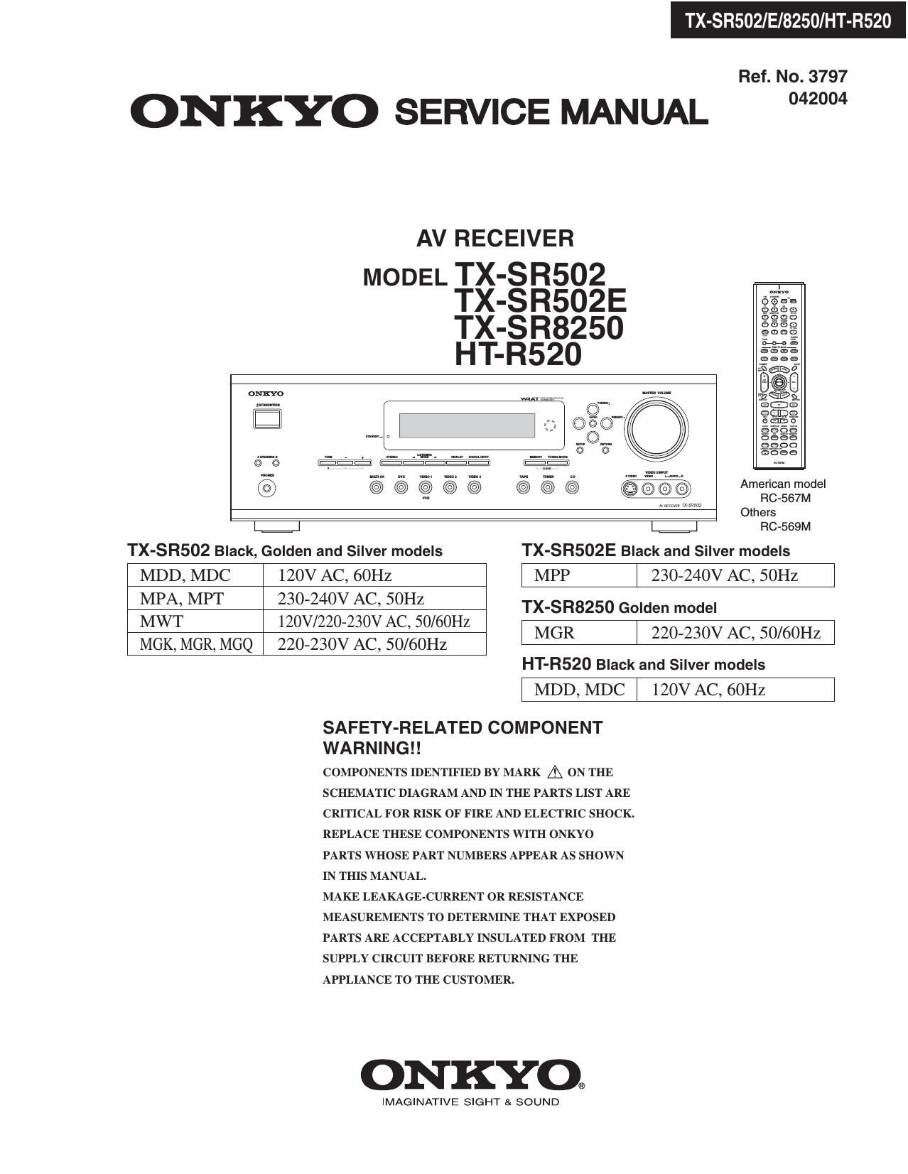
Onkyo TXSR 502 Service Manual

This is the 117 pages manual for Onkyo TXSR 502 Service Manual.
Read or download the pdf for free. If you want to contribute, please mail your pdfs to info@audioservicemanuals.com.

Page: 1 / 117
left right
Onkyo TXSR 502 Service Manual

Extracted text from Onkyo TXSR 502 Service Manual (Ocr-read)


Page 1

TX-SRSOZ/E/8250/HT-R520

Ref. No. 3797

ONKYO SERVICE MANUAL 2"

AV RECEIVER

MODEL TX-SR502
TX-SR502E
TX-SR825O
HT-R520

56130"
mm 908
m... E3;
l: 3%?
{sf-((33 513..
@
Others
L.=.J RC-SGQM
TX-SR502 Black, Golden and Silver models TX-SR502E Black and Silver models
MDD, MDC 120V AC, 60Hz l MPP | 230-240V AC, SOHZ l
35% M f§§§3§§ovz§§vi%H§O/60H TX'S825°G°'""°'
- , z
MGK, MGR, MGQ 220-230V AC, 50/60Hz MGR I 220230" AC 50mm

HT-R520 Black and Silver models

l MDD,MDC | 120VAC, 60Hz l

SAFETY-RELATED COMPONENT
WARNING! !

COMPONENTS IDENTIFIED BY MARK A ON THE
SCHEMATIC DIAGRAM AND IN THE PARTS LIST ARE

CRITICAL FOR RISK OF FIRE AND ELECTRIC SHOCK.

REPLACE THESE COMPONENTS WITH ONKYO
PARTS WHOSE PART NUMBERS APPEAR AS SHOWN
IN THIS MANUAL.

MAKE LEAKAGE-CURRENT OR RESISTANCE
MEASUREMENTS TO DETERMINE THAT EXPOSED
PARTS ARE ACCEPTABLY INSULATED FROM THE
SUPPLY CIRCUIT BEFORE RETURNING THE
APPLIANCE TO THE CUSTOMER.

ONKYO.

IMAGINATIVE SIGHT & SOUND

Page 50

IC BLOCK DIAGRAM AND TERMINAL DESCRIPTIONS-6
0301: BD3817KS (7ch Volume with 10ch input selector)-3

TERMINAL DESCRIPTION

Pin No. Pin Name Description
87 VEE (-)Power supply terminal
88 NC Non-connected terminal
89 VCC (+)P0wer supply terminal
90 AGND13 Analog ground terminal
91 ROUTAl lch REC input and output terminal A
92 ROUTAZ 2ch REC input and output terminal A
93 ROUTBI lch REC output terminal B
94 ROUTB2 2ch REC output terminal B
95 ROUTCl lch REC output terminal C
96 ROUTC2 2ch REC output terminal C
97 OUT1 lch output terminal
98 OUT2 2ch output terminal
99 AGND 14 Analog ground terminal
100 AGND 15 Analog ground terminal

502/E/8250/HT-R520

Page 72

OPERATION CHECK-2
OUTPUT LEVEL & THERMAL DETECTION

Regarding the power supply system of this unit.

l. High-voltage mode
Usually, the power supply supplies high voltage to the power amplifier circuit when the relay(RL6901) is turned on.
2. Low»voltage mode
When as follows, a power supply changes to the state of supplying low voltage when the relay (RL6901) in turned off.
(1) Excessive output signal is continuously outputted from power amplifier.
(2) Temperature of a heat sink over 80 degrees

1. The loss which power amplifier generates is decreased. As a result, the miniaturization of a heat sink is realized.
2. Corresponds to a safety standard.

+51
RLst High 1 5501 3
SPEAKER ;
om TX-SFl502 HT-Fl520 3 ;
POWER AMP. fl» sozEI/szso . 3
1 '6 +/- 53 o v +/- as o v 1
MODE - - 1 ;
ouwuw Low 1 1
+/- 35.0 v +/- 33.5 v .
LEVEL MODE RL5902 1
DETECTION 1 l
'B 1 T901 MAIN 1
THERMAL JRANSFOHMEH 1
SENSOR L ,,,,,,,,,,,,,,,,,
335° ,- 5???ng seem
6303 . t VOL 07009 23 -» 05901
O 2 MAIN
MICROPHOCESSOH

May not notice the fuse (F6901, F6902) broken in the case of repair.

Because the power supply is continuing supplying voltage from the High side of SECl at high»voltage mode.
When a power supply Circuit changes to low voltage mode, amplifier does not operate.

Therefore, it is very important to check operation of this power supply system containing a fuse.

[NOTEZ]

Don't connect speakers or any load.

Don't short speaker terminals.

(1) Set the unit is Multi channel input state.

(2) Set the master volume into the minimum.

(3) Apply sine wave signal to MULTI CHANNEL INPUT (FL+FR+C+SL) terminals.
(4) Connect an oscilloscope to speaker terminal of FL channel.

(5) Adjust master volume so that a speaker output may become distortion about 5%.

High-voltage

(6) Check that the RL6901 is turned off after about 5 seconds.
And the power supply changes to low-voltage mode.

Low-voltage

(7) Adjust the master volume so that output voltage may become half.

AV

(8) Check that the RL6901 is turned ON after 2 to 3 minutes.
And the power supply returns to high-voltage mode.