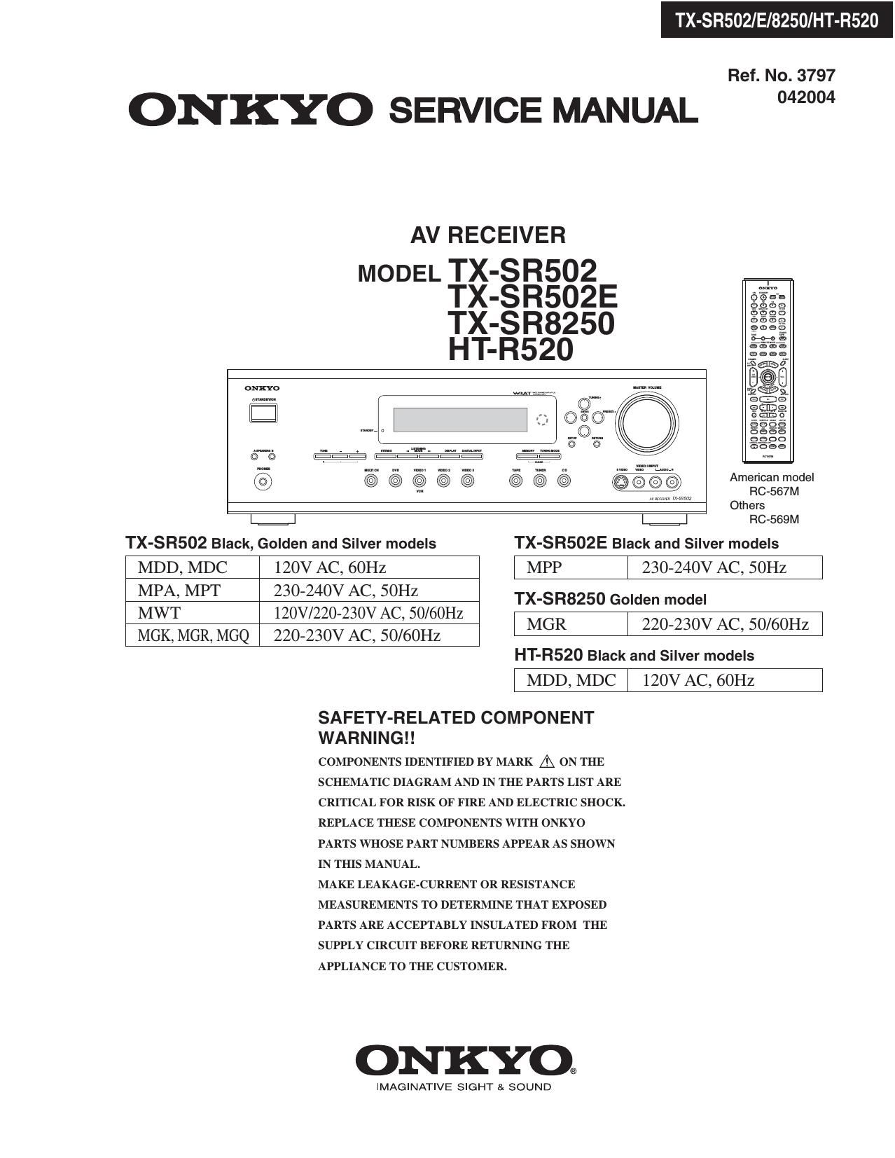
Onkyo TXSR 502 E Service Manual

This is the 117 pages manual for Onkyo TXSR 502 E Service Manual.
Read or download the pdf for free. If you want to contribute, please mail your pdfs to info@audioservicemanuals.com.

Page: 1 / 117
left right
Onkyo TXSR 502 E Service Manual

Extracted text from Onkyo TXSR 502 E Service Manual (Ocr-read)


Page 1

TX-SRSOZ/E/8250/HT-R520

Ref. No. 3797

ONKYO SERVICE MANUAL 2"

AV RECEIVER

MODEL TX-SR502
TX-SR502E
TX-SR825O
HT-R520

56130"
mm 908
m... E3;
l: 3%?
{sf-((33 513..
@
Others
L.=.J RC-SGQM
TX-SR502 Black, Golden and Silver models TX-SR502E Black and Silver models
MDD, MDC 120V AC, 60Hz l MPP | 230-240V AC, SOHZ l
35% M f§§§3§§ovz§§vi%H§O/60H TX'S825°G°'""°'
- , z
MGK, MGR, MGQ 220-230V AC, 50/60Hz MGR I 220230" AC 50mm

HT-R520 Black and Silver models

l MDD,MDC | 120VAC, 60Hz l

SAFETY-RELATED COMPONENT
WARNING! !

COMPONENTS IDENTIFIED BY MARK A ON THE
SCHEMATIC DIAGRAM AND IN THE PARTS LIST ARE

CRITICAL FOR RISK OF FIRE AND ELECTRIC SHOCK.

REPLACE THESE COMPONENTS WITH ONKYO
PARTS WHOSE PART NUMBERS APPEAR AS SHOWN
IN THIS MANUAL.

MAKE LEAKAGE-CURRENT OR RESISTANCE
MEASUREMENTS TO DETERMINE THAT EXPOSED
PARTS ARE ACCEPTABLY INSULATED FROM THE
SUPPLY CIRCUIT BEFORE RETURNING THE
APPLIANCE TO THE CUSTOMER.

ONKYO.

IMAGINATIVE SIGHT & SOUND

Page 69

MICROPROCESSOR TERMINAL DESCRIPTIONS-2

Q7502:MPD780232GC-030-8BT(SUB MICROPRCESSOR)

No. Pin name I/O Description No. Pin name |/O Description
1 VDDl 1 Power supply terminal. Connect to 5V. 41 P22 0 Segment output terminal of P22.
2 VSSl 1 Ground terminal. 42 P21 0 Segment output terminal of P21.
3 X1 I Xtal input terminal. 43 P20 0 Segment output terminal of P20.
4 X2 0 Xtal input terminal. 44 P19 0 Segment output terminal of P19.
5 IC 1 Connect to ground. Not used. 45 P18 0 Segment output terminal of P18.
6 ~RESET 1 System reset signal input terminal. 46 P17 0 Segment output terminal of P17.
7 SUB CL/SCK I Clock input terminal to transmit the 47 P16 0 Segment output terminal of P16.
Emil from main 115ml7r 059350 48 P15 0 Segment output terminal of P15.
Data input terminal to transmit the signal 49 P14 0 Segment output terminal of P14.
8 SUBDO/SDI I from main micrOProcessor- 50 P13 0 Segment output terminal of P13.
Data output terminal to transmit the signal 51 P12 0 Segment output terminal of P12.
9 SUBDVSDO O to main microprocessor. 52 P11 0 S t t tt - .1 f Pll
. egmen ou pu ernuna o .
10 SUBRDY O 3:: Eidrym 21:33:; timid to transmit to 53 P10 0 Segment output terminal of P10.
54 P9 0 Segment output ternunal of P9.
11 VB J 1 Pulse input terminal from the rotary encoder 55 P8 0 Segment output terminal of P8.
0f volume. 56 P7 0 Segment output terminal of P7.
12 VA] 1 5:15:13? terminal from the rotary encoder 57 P6 0 Segment output terminal or P6.
58 P5 0 Segment output terminal of P5.
13 ~SYSIN 1 System code input terminal- 59 VDD2 1 Power supply terminal. Connect to +5v.
l4 ~SYSOUT 0 System code output terminal. 60 V'LOAD 1 Negative power supply terminal of FL
15 ~IRIN I Not used. controller.
16 ~IRF I Signal input terminal from the remote 61 P4 0 Segment output terminal of P4.
controller. 62 P3 0 Segment output terminal of P3.
17 STBYLED O Standby LED control output terminal. 63 1:2 0 Segment output terminal of P2.
18 AVSS 1 Ground terminal for AID converter. 64 P1 0 Segment output terminal of P1.
19 K3 1 Operation key connection terminal-3. 65 160 0 Grid output terminal of 166.
20 K2 I Operation key connection terminal-2. 66 150 0 Grid output terminal of 15G.
21 K1 I Operation key connection terminal-1. 67 140 0 Grid output terminal of 14G.
22 K0 I Operation key connection terminal-0. 68 13G 0 Grid output lem'iinal of 130.
23 VSSO 1 Ground terminal. 69 12G 0 Grid output terminal of 12G.
24 AVDD I Power supply terminal for A/D converter. 70 110 0 Grid output terminal of 1 1G.
25 VDDO I Power supply terminal. Connect to +5V. 71 10G 0 Grid output terminal of 10G.
26 NU --- Not used. 72 9G 0 Grid output terminal of 9G.
27 PURE O PURE AUDIO LED control output terminal. 73 8G 0 Grid output terminal of 8G.
28 P35 0 Segment output terminal of P35. 74 7G 0 Grid output terminal of 7G.
29 P34 0 Segment output terminal of P34. 75 6G 0 Grid output terminal of 6G.
30 P33 0 Segment output terminal of P33. 76 5G 0 Grid output terminal of SG_
31 P32 0 Segment output terminal of P32. 77 4G 0 Grid output terminal of 4G.
32 P31 0 Segment output terminal of P31. 73 3G 0 Grid output [en-fling of 3G.
33 P30 0 Segment output terminal of P30. 79 2G 0 Grid output terminal of 2G.
34 P29 0 Segment outpul Iennin'dl of P29- 80 1G 0 Grid output terminal of 1G.
35 P28 0 Segment output terminal of P28.
36 P27 0 Segment output terminal of P27.
37 P26 0 Segment output terminal of P26.
38 P25 0 Segment output terminal of P25.
39 P24 0 Segment output terminal of P24.
40 P23 0 Segment output terminal of P23.