Onkyo TXSR 333 Service Manual

This is the 79 pages manual for Onkyo TXSR 333 Service Manual.
Read or download the pdf for free. If you want to contribute, please mail your pdfs to info@audioservicemanuals.com.

Page: 1 / 79
left right
Onkyo TXSR 333 Service Manual

Extracted text from Onkyo TXSR 333 Service Manual (Ocr-read)


Page 1

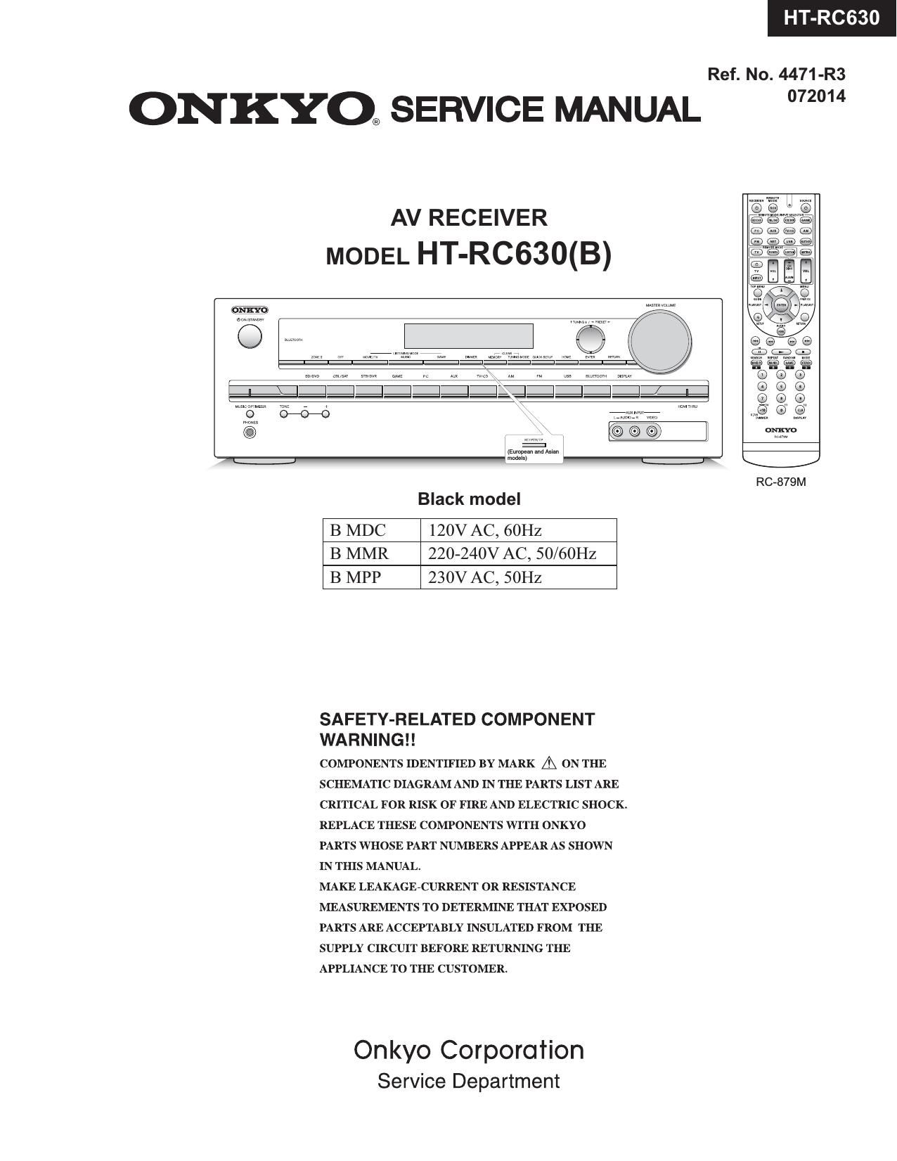
HT-RC630

Ref. No. 4471-R3

ONKYO® SERVICE MANUAL 2°

AV RECEIVER
MODEL HT-RC630(B)

Black model

B MDC 120V AC, 60Hz
B MMR 220-240V AC, 50/60Hz
B MPP 230V AC, SOHZ

SAFETY-RELATED COMPONENT
WA R N I N G ! !

COMPONENTS IDENTIFIED BY MARK A ON THE
SCHEMATIC DIAGRAM AND IN THE PARTS LIST ARE
CRITICAL FOR RISK OF FIRE AND ELECTRIC SHOCK.
REPLACE THESE COMPONENTS WITH ONKYO
PARTS WHOSE PART NUMBERS APPEAR AS SHOWN
IN THIS MANUAL.

MAKE LEAKAGE-CURRENT OR RESISTANCE
MEASUREMENTS TO DETERMINE THAT EXPOSED
PARTS ARE ACCEPTABLY INSULATED FROM THE
SUPPLY CIRCUIT BEFORE RETURNING THE
APPLIANCE TO THE CUSTOMER.

Onkyo Corporation
Service Department

Page 2

DEBUG MODE-1

AUDIO DEBUG MODE-1/5

TX-SR333/ HT-R393/ HT-RC630

The operations of DSP and DIR etc are able to checked by the information displayed on FL in this debug mode.
This information will help to analysing digital audio no sound trouble,

To set in Debug mode

1. Press twice the ON/ STANDBY key while pressing the DISPLAY key.

e.g.

M1.03/14307ALN*

The version number of Microprocessor is displayed
only for 3 seconds

2 Press + (TONE) button while the version number of microprocessor is displayed.

e.g.

N1 02/14210ALA _ The version number of DSP is displayed

3. Press DISPLAY button while the version number of DSP is displayed.

e.g.

0A0002. :00

Step-1

4. Proceed to the next step by pressing the DISPLAY key.

ANA:o:NON:C:
4v

1:ANA 048k048k
4v

2/00: 2.0:3/4
4v

2:0:PCM :PCM
4v

00:X:F:OFF

4v

SPO0F*00F00409
4v

48 482568TB
4v

L :0000 0000

v;

S W :0000 0000

4v

Step-2

Step-3

Step-4

Step-5

Step-6

Step-7

Step-B

Exit

only for 3 seconds

AUDIO dubug mode
The status of DSP and DIR etc
will be displayed.

Page 21

SR333/ HT-R393/ HT-RC630

OPERATION CHECK-8

TEST 4.oo~4.24 Auto Measurement Mode

TEST DSP Outputchannel DSP DSP Config. Master Speaker

No. Output Output Vol. Relay

F uen Volta

4-00 ALL zlSWfiOHU -20dBFS
4-01 ALL ZISWMZI -20dBFS
4-02 ALL 20kHz -20dBFS
4-03 SW 30Hz -20dBFS
4-04 FL FR 30Hz -20dBFS
4-05 ALL ZISWBOHZI -20dBFS
4-06 ALL ZISWBOHU -20dBFS
4-07 FR C SL SR SW 10kHz -20dBFS
4-08 FLCSLSR SW 10kHz -20dBFS
4-09 FL FR SL SR SW 10kHz -20dBFS
4-10 FL FR C SR SW 10kHz -20dBFS
4-11 FL FR C SL SW 10kHz -20dBFS

64 Re F CS DSP Gain

64 Re F CS DSP F .R onse
58 76 F CS Characteristic 1

64 Re F CS Characteristic 2

64 R F CS Mu 0n Mqun

Min Min F CS Volume Max.Attenuation
64 Re F CS Mute:FL Se aration FL

64 Re F CS Mute:FR Se aration FR

64R FC Mu :C Sea tionC

64 Re F CS Mute:SL Se aration SL

64 Re F CS Mute:SR Se aration SR

-<-<-<<-<-<-

4-14 FL FR C SL SR 30Hz -20dBFS 64 Re F CS Mute:SW Se aration SW

4-19 FL +DC +Max Max Max F CS *1 *3 +DC Pro FL
4-20 FR -D -Max Max Max F C *1 *3 -D Prote FR
4-21 C +DC +Max Max Max F CS *1 *3 +DC Pro C

4-22 SL -DC -Max Max Max F CS *1 *3 -DC Prote SL
4-23 SR +DC +Max Max M x F CS *1 *3 +DC Pro SR
4-24 SW -DC -Max Max Max F CS *1 *3 -DC Prote SW

*1 All SP-RELAYs are turned ON only at the time of this STEP.
Moreover, whether make RELAY restoration time at the time of protection operation into 1 second, and PROTECT input "H" is detected
how many times or it continues 1 second or more, RELAY is not held at OFF or POWER OFF is not carried out, either.
When "H" is 1 seconds or more to PROTECT input and it is set to '"L RELAY is turned ON again.
Moreover, not any MUTE is outputted at the time of this STEP.

*3 If voltage-detection protector check in TEST-1-01 starts, DC voltage is output immediately from each channel. (within 100msec.)

*4 The following signal is output from all channel continuously in TESTt-OB.

1W

IMAX

Ksia-msi

20mS

*5. VOLH is detected and H/L of SEC1 H is changed.
A detection level is the same as the normal mode.
When it is detected, light "FM STEREO" on FL TUBE.

6 PRRLF=ON
*7 In TEST 1-06, some character is displayed while pushing down some button. Another character shall be displayed by each button.

[NOTES]

: DSP Thru of Listening Mode outputs L Input signal to L/C/SL, and outputs R Input signal to R/SR/SW.

: Config. is in order of SW/FronI/Center/Surround.

: Mute is function to stop output(from the channel) by using inner DSP programming.

: When Listening Mode is DSP thru, an analog SW is changed into the state of SURROUND.

:At the time of PRTCTTHM detection, it is displayed on FLT as "THERMAL PROTECT".

: In all test modes, it is not concerned with detection of VOLH but SEC1 H are made "H" fixation. (Except TEST 1-07 and 1-08.)
: TEST of NET/USB can't do immediately after the start-up.

It should be measure after other TEST.

After initialization of Net or USB, start TEST 1-04.

\tosmAcoN-t

9?

Page 26

HT-RC630

EXPLODED VIEW
OVERALL


No description screw is 3TTB+SB(BBC). 3TTB+8|3(BC)

8

3i:

Unit: mm

>l< WiFi & Bluetooth Module has already been certificated by FCC and IC.

Information to the user.
Indicate "Contains FCC ID: TX2-RTL8723AS", "Contains IC: 6317A- RTL8723AS" and following information to the
host device installed.

3P+6FN(3BC)


This device complies with part 15 of the FCC Rules. Operation is subject to the following two conditions: (1) This
device may not cause harmful interference, and (2) this device must accept any interference received, including
interference that may cause undesired operation.

Describe the following sentence to a users manual of the host device.
[For FCC]

FCC CAUTION

Changes or modifications not expressly approved by the party responsible for compliance could void the user's
authority to operate the equipment.

Note: This equipment has been tested and found to comply with the limits for a Class B digital device, pursuant

to part 15 of the FCC Rules. These limits are designed to provide reasonable protection against harmful interference
in a residential installation. This equipment generates, uses and can radiate radio frequency energy and, if

not installed and used in accordance with the instructions, may cause harmful interference to radio communications.
However, there is no guarantee that interference will not occur in a particular installation. If this equipment

does cause harmful interference to radio or television reception, which can be determined by turning the

equipment off and on, the user is encouraged to try to correct the interference by one or more of the following
measures:

-Reorient or relocate the receiving antenna.

-lncrease the separation between the equipment and receiver.

-Connect the equipment into an outlet on a circuit different from that to which the receiver is connected.

-Consult the dealer or an experienced radio/TV technician for help.

Rear Panel

This transmitter must not be co-located or operated in conjunction with any other antenna or transmitter.
4TTC+BC(3BC)SR
This equipment complies with FCC radiation exposure limits set forth for an uncontrolled environment and meets
the FCC radio frequency (RF) Exposure Guidelines in Supplement C to 0ET65. This equipment has very low

levels of RF energy that it deemed to comply without maximum permissive exposure evaluation (MPE). But it is 8
desirable that it should be installed and operated keeping the radiator at least 20cm or more away from persons
body (excluding extremities: hands, wrists, feet and ankles). Hi 4 i:

[For IC] x 4 pcs.
CAN ICES-3 B/NMB-3 B T901

This device complies with Industry Canada licence-exempt RSS standard(s). Operation is subject to the following
two conditions: (1) this device may not cause interference, and (2) this device must accept any interference,
including interference that may cause undesired operation of the device.

Le present appareil est conforme aux CNR d'lndustrie Canada applicables aux appareils radio exempts de
licence. L'exploitation est auton'sée aux deux conditions suivantes : (1) l'appareil ne doit pas produire de
brouillage, et (2) l'utilisateur de l'appareil doit accepter tout brouillage radioélectrique subi, meme si le brouillage
est susceptible d'en compromettre le fonctionnement.

g
This equipment complies with IC radiation exposure limits set forth for an uncontrolled environment and meets /<
RSS»102 of the IC radio frequency (RF) Exposure rules. This equipment has very low levels of RF energy that it
deemed to comply without maximum permissive exposure evaluation (MPE). But it is desirable that it should be 3TTB+8B(SCM)SR
installed and operated keeping the radiator at least 20cm or more away from person's body (excluding extremities:
hands, wrists, feet and ankles).
Cet équipement est conforme aux limites d'exposition aux rayonnements énoncées pour un environnement non
controlé et respecte les regles dexposition aux fréquences radioélectriques (RF) CNR-102 de I'IC. Cet équipement
emet une énergie RF trés faible qui est considérée conforme sans evaluation de l'exposition maximale
autorisée. Cependant, cet équipement doit étre installé et utilise en gardant une distance de 20 cm ou plus entre
le dispositif rayonnant et Ie corps (a lexception des extrémités : mains, poignets, pieds et chevilles).

* U791A
WiFi & Bluetooth Module

/
uo1zoB g

* This module transmitter does not have RF shielding, 3SMS&W.SW+14B(CU)
therefore it will be equipped only the tested Audio system [17913 FFC
mentioning this document. 2 6TI'B+8B(SBC) p101
Additional test will be required it it will be equipped to the ' 7
other devices 14
7
U791(W|Fl MODULE) = U791A + U791B + U791C 44 3i:
x 10 pcs
j uoo12 uoo11 5
5 4L 5
: ® 0 W o o @9 o :
e e e m
69 O Heatsink ® 0
A205\\ E 5
A23»: 5 i
A213 06054 06064 06052 06062 06050 06060

06053 06063 06051 06061