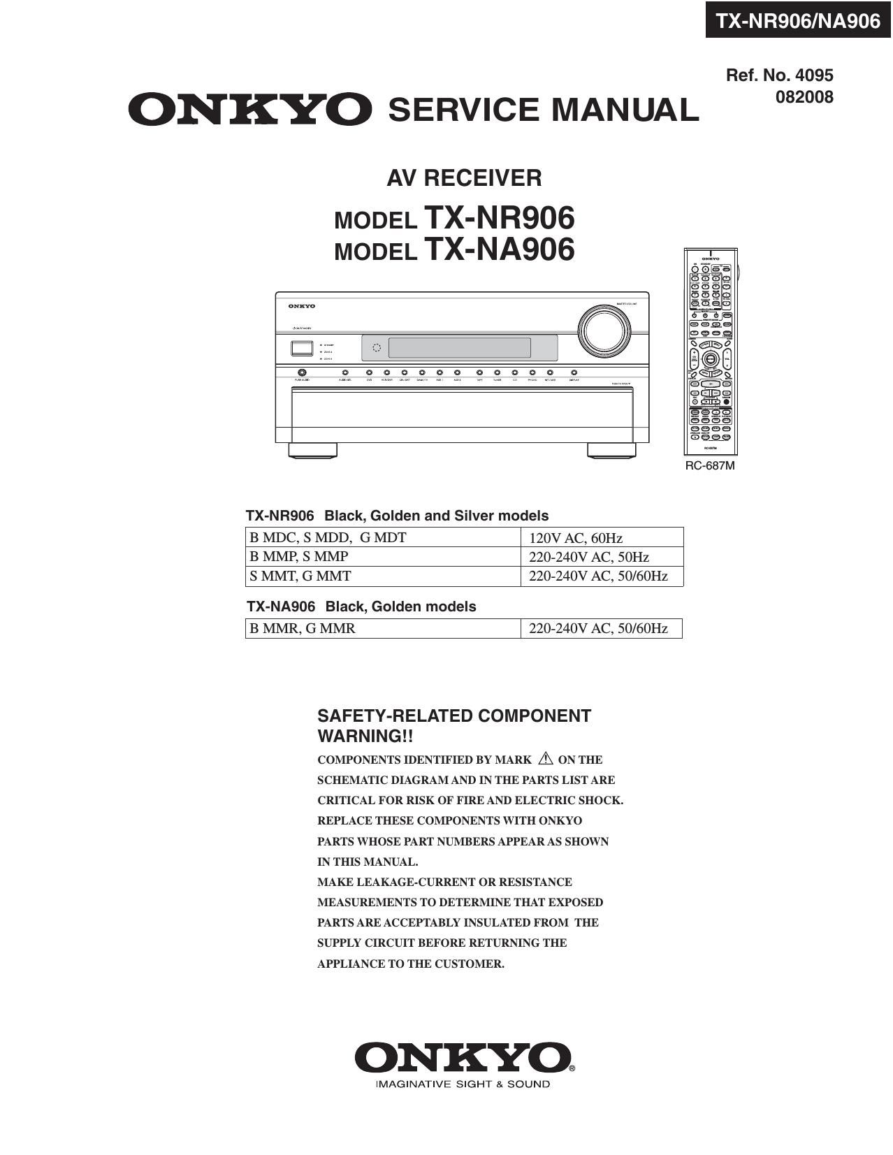
Onkyo TXNR 906 Service Manual

This is the 336 pages manual for Onkyo TXNR 906 Service Manual.
Read or download the pdf for free. If you want to contribute, please mail your pdfs to info@audioservicemanuals.com.

Page: 1 / 336
left right
Onkyo TXNR 906 Service Manual

Extracted text from Onkyo TXNR 906 Service Manual (Ocr-read)


Page 1

TX-NR906/NA906

Ref. No. 4095
ON KYO SERVICE MANUAL 2°
AV RECEIVER
MODEL TX-N R906
MODEL TX-NA906 SEQ

(nHaIaH

TX-NR906 Black, Golden and Silver models

B MDC, S MDD, G MDT 120V AC, 60Hz
B MMP, S MMP 220-240V AC, 50Hz
S MMT, G MMT 220-240V AC, 50/60Hz

TX-NA906 Black, Golden models
13 MMR, G MMR | 220-240v AC, 50/60Hz

SAFETY-RELATED COMPONENT
WA R N I N G ! !

COMPONENTS IDENTIFIED BY MARK A ON THE
SCHEMATIC DIAGRAM AND IN THE PARTS LIST ARE
CRITICAL FOR RISK OF FIRE AND ELECTRIC SHOCK.
REPLACE THESE COMPONENTS WITH ONKYO
PARTS WHOSE PART NUMBERS APPEAR AS SHOWN
IN THIS MANUAL.

MAKE LEAKAGE-CURRENT 0R RESISTANCE
MEASUREMENTS TO DETERMINE THAT EXPOSED
PARTS ARE ACCEPTABLY INSULATED FROM THE
SUPPLY CIRCUIT BEFORE RETURNING THE
APPLIANCE To THE CUSTOMER.

ONKYO®

IMAGINATIVE SIGHT SI SOUND

Page 2

NR90 NA90

IC BLOCK DIAGRAMS AND TERMINAL DESCRIPTIONS -48
08901: ADV7320 (Video Encoder with Six 12-bit DACs)

TERMINAL DESCRIPTION
Pin No. Mnemonic Input/Output Description
11.57 DGND G DigitalGround.
40 AGND 6 Analog Ground.
32 CLKlNiA l Pixel Clock Input for HD Only £74.25 MHZ), P5 Only (27 MHZ), and SD Only (27 MHZ].
|

63 CLKlNiB Pixel Clock Input. Requires a 27 MHZ reference clockfor PS mode or a 74.25 MHZ (74.1 758 MHZ)

reference clock in HDTV modeThis clock is only used in dual modes.

45, 36 COMPI, 0 Compensation Pin for DACs. Connect 0.1 pF capacitorfrom COMP pin to VAA.
COMPZ

44 DAC A O CVBS/Green/Y/Y Analog Output.

43 DAC B O Chroma/Blue/U/Pb Analog Output.

42 DAC C O Luma/RedN/PrAnalog Output.

39 DAC D O In SD Only Mode: CVBS/Green/Y Analog Output; in HD Only Mode and Simultaneous HD/SD
Mode: Y/Green [HD] Analog Output.

38 DACE O In SD Only ModezLuma/Blue/U Analog Output7in HD Only Mode and Simultaneous HD/SD
Mode: Pr/Red Analog Output.

37 DACF O In SD Only Mode: Chroma/Red/V Analog Output; in HD Only Mode and Simultaneous HD/SD
Mode: Pb/Blue [HD] Analog Output.

23 P7HSYNC I Video Horizontal Sync Control Signal for HD in Simultaneous SD/HD Mode and HD Only Mode.

24 P7VSYNC I VIdeoVertical Sync Control Signal for HD in Simultaneous SD/HD Mode and HD Only Mode.

25 PiBLANK I Video Blanking Control Signal for HD in Simultaneous SD/HD Mode and HD Only Mode.

48 SiBLANK I/O Video Blanking Control Signal for SD Only.

49 S,VSYNC l/O Video Vertical Sync Control Signal for SD Only.

50 57H SYNC I/O Video Horizontal Sync Control Signal for SD Only.

13,12, Y9 to Yo | SD or PS/HDTV Input Port forY Data. Input port for interleaved progressive scan data.The LSB

9 to 2 is set up on Pin YO. Forsrbit data input, LSB is setup on Pin Y2.

30 to 26, C9 to CO | PS/HDTV Input Port 4:4:4 Input ModeThis port is used for the Cb[BIue/U] data. The LSB is set

18 to 14 up on Pin CO. For 8-bit data input, LSB is set up on Pin C2.

Pin No. Mnemonic Input/Output Description

62 to 58, 59 to SO | SD orPS/HDTVInput Port forCr[RedN] Datain 4:4:4lnput Mode. LSBis set up on Pin SO. For

55 to 51 87bit datainput,LSBis set up on Pin 52.

33 W | This input resets the on-chip timing generatorand sets the ADV7320/ADV7321 into default
register setting. RESETis an active low signal.

47, 35 Ram, Ran, l A 3040 Q resistor must be connected from this pin to AGND and is used to control the
amplitudes ofthe DAC outputs.

22 SCLK I IIC Port Serial Interface Clock Input.

21 SDA l/O llC Port Serial Data Input/Output.

20 ALSB l TTL Address lnput.This signal sets up the LSB ofthe IZC address. When this pin is tied low, the
IZC filter is activated, which reduces noise on the PC interface.

I Vmiu P Power Supply for Digital Inputs and Outputs.

10,56 VoD P Digital Power Supply.

41 VAA P Analog Power Supply.

46 VREF I/O Optional External Voltage Reference Input for DACs or Voltage Reference Output (1235 VI.

34 EXT7LF I External Loop Filterfortne internal PLL.

3i RTC75CR7TR l Multifunctional Input. Real»time control (RTCI in put, timing reset input, subcarrier reset input.

19 IZC | This input pin must be tied high (VDDVIOJ forthe ADV7320/ADV7321 to interface over the PC port.

64 GNDiiO Digital Input/Output Ground.

Page 80

TX-NR906/NA906

IC BLOCK DIAGRAMS AND TERMINAL DESCRIPTIONS -12
04305: NJU7313AM (Analog Function Switch)

BLOCK DI AGRAM

L1 R1
L2 0 R2
L3 R3
L4 R4
L-COM1 o g E E g R-COM1
6 <3 '6 6
L5 - 5 J; _ R5
2 o o 9
a.) a E 0)
L6 4 4 4 _l R6
L-COM2 O Fi-COM2
L7 R7
L8 R8
L-COM3 0 R-COM3
ST DATA
VDD 0 CK
VEE I VSS
TERMINAL DESCRIPTION
Pin No. Pin Name Description Pin No. Pin Name Description
1 VEE Negative Voltage Supply 16 CK Clock input
2 L1 Analog switch input/output l7 DATA Data input
3 L2 Analog switch input/output l9 R-COM3 R7, R8 Common
4 L3 Analog switch input/output 20 R8 Analog switch input/output
5 L4 Analog switch input/output 21 R7 Analog switch input/output
6 L-COMl L1, L2, L3, L4 Common 22 R-COM2 R5, R6 Common
7 LS Analog switch input/output 23 R6 Analog switch input/output
8 L6 Analog switch inpquutput 24 R5 Analog switch input/output
9 L-COM2 L5, L6 common 25 R-COMl R1, R2, R3, R4 Common
10 L7 Analog switch input/output 26 R4 Analog switch input/output
ll L8 Analog switch input/output 27 R3 Analog switch input/output
12 L-COM3 L7, L8 Common 28 R2 Analog switch input/output
14 ST Chip enable 29 R1 Analog switch input/output
15 V88 GND 30 VDD Positive voltage supply