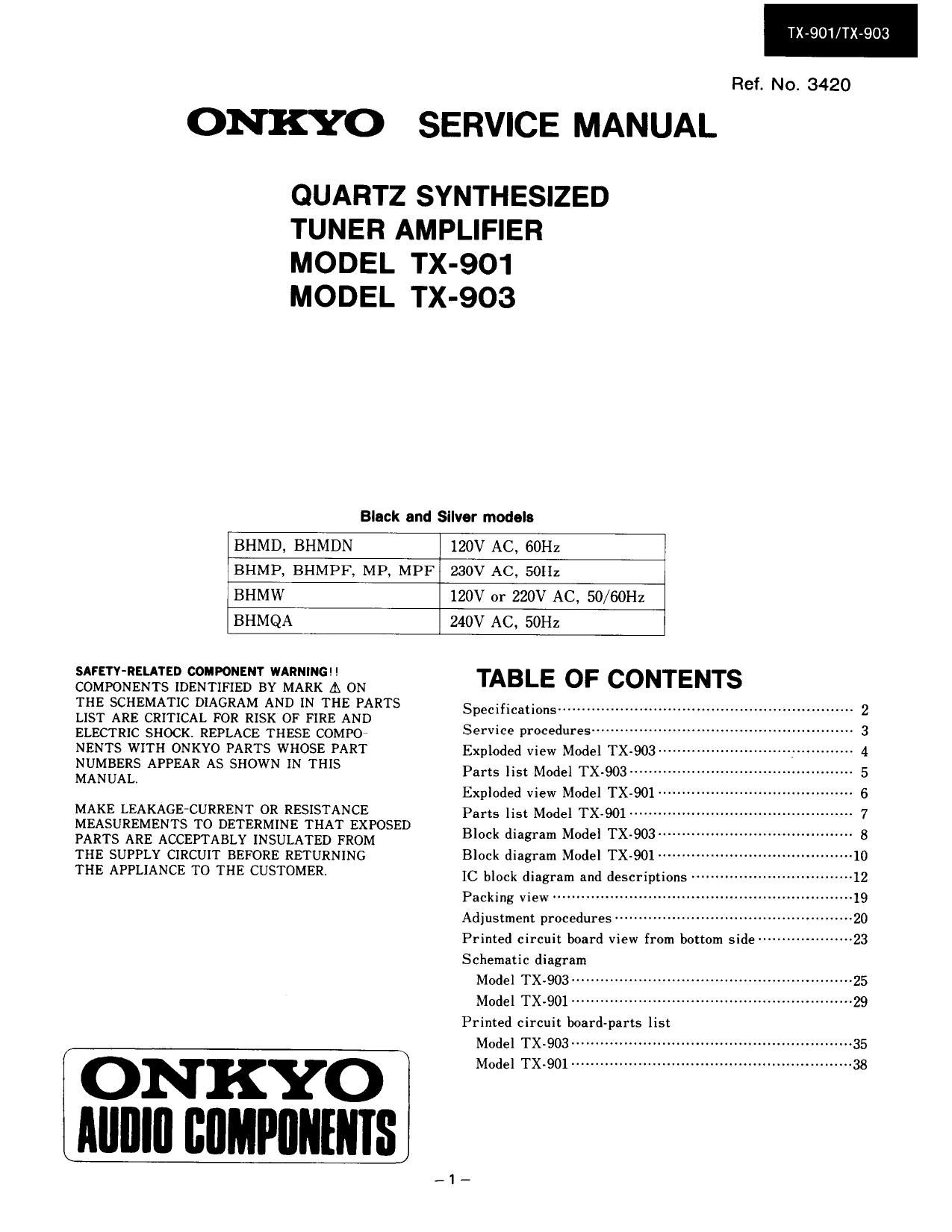
Onkyo TX 901 Service Manual

This is the 30 pages manual for Onkyo TX 901 Service Manual.
Read or download the pdf for free. If you want to contribute, please mail your pdfs to info@audioservicemanuals.com.

Page: 1 / 30
left right
Onkyo TX 901 Service Manual

Extracted text from Onkyo TX 901 Service Manual (Ocr-read)


Page 1

TX-901/TX-903

Ref. No. 3420

ONKYO SERVICE MANUAL

QUARTZ SYNTHESIZED
TUNER AMPLIFIER
MODEL TX-901
MODEL TX-903

Black and Silver models

BHMD, BHMDN

120V AC, 60Hz

BHMP, BI-IMPF, MP. MPF

230V AC, 50H:

BHMW

120V or 220V AC. 50/60I-Iz

BHMQA

240V AC, 50Hz

SAFETY-RELATED COMPONENT WARNING l!
COMPONENTS IDENTIFIED BY MARK A ON
THE SCHEMATIC DIAGRAM AND IN THE PARTS
LIST ARE CRITICAL FOR RISK OF FIRE AND
ELECTRIC SHOCK. REPLACE THESE COMF'O
NENTS WITH ONKYO PARTS WHOSE PART
NUMBERS APPEAR AS SHOWN IN THIS
MANUAL.

MAKE LEAKAGEiCURRENT OR RESISTANCE
MEASUREMENTS TO DETERMINE THAT EXPOSED
PARTS ARE ACCEPIABLY INSULATED FROM

THE SUPPLY CIRCUIT BEFORE RETURNING

THE APPLIANCE TO THE CUSTOMER.

ON KYO
Mllllll llllMPllllfllIS

TABLE OF CONTENTS

Specifications ..........

Service procedures-U
Exploded view Model TX-903 ------
Parts list Model TX.9()3 ............
Exploded view Model TX-901 ------
Parts list Model TX-901 ------------
Block diagram Model TX-903 ------
Block diagram Model TX-901
IC block diagram and descriptions --

Packing view .................

Adjustment procedures-
Printed circuit board view from bottom side ------------------- 23
Schematic diagram
Model "TX-903""
Model TX-901
Printed circuit boardparts list
Model TX-903~~
Model TX-901

Page 10

TX-901

$5.25..
«muusm 3; .6 z o»
itizu» n: .3... wimp... t! um _
neat?
_J.® Q a; =2 _ m _
+ _
. _ c
.32.:wa 233
9.3%
u and in on in 2.3.6 :6 momma...
SEER. 2.5 I
N358 58 23
s 1%!
a.
wine 1
>39. M
van mono 5.26 L m
9:3 3 I
nmnc u w
H
M
5mm: 9
voua n
a
~ .33. a
u x w 1 1% \# ozoxm
u a; .. m v E: _
w a a .. $5.33
a
.. .. M .30
can. 7.3.2 62 Roiuommflola in
333335.: :3 I? on
53 bod I
s in
..
n n a s
M n xiii a
uni n o rmv. z_ .2
>525 55.6% 621.. 391..
EH 54.63.80 4 u n... :6
was... 553be ..._m
in 539. am. mm? d was ~_mm._w
6mm 35 h m
o . . .
am mi... s . H
o 19.3..
020: \ or... 4. one 03 _
w h .28.. .2 oz 59: in
1 . «a» 503
w m m , . mm» M
xfi ups: a A_n mw u. 4 wk :1 o xuozofifll. 3w uu< m w
«80 w I nos
P E 4 MA»)? m mm} .nidn... u _n_.. . u m
..
s _ a _ A u _ . . E .
tonoo ma oslz. w 39¢. :3 .E. mwxi 13 m: w w
2 a ti ll
fl)? xmuouwo oumufi 3:5 as: :4 an: E m. E Ti 1
~03 w m 83 m 36 5 C «E .5 m n
)6 ms: m I. . . W m
mono an N _ _[.|I.|.1|L m
C :5 :<

53:. docs
SEE-050 v.00._m

_|0_

Page 12

TX-901/TX-903

,u PD1 71 03CX-528(Remote control decoder)

MODEL TX-903

Bus
- U701 Q703 Q705 line
Transmitter fl Preamp. -> Remote control -> Buffer ->
decoder
Infrared
x IN E :6] GND
x OUT E E] P0132 -> STAND-BY
RESET E E P0131 -> RECEIVE
REMIN ->P0Do E EPOBOfiVOLIND
PH SENS -> PODl E E POC3 -> VOLUP
POWER ~» PODZ E E] POC2 -* VOL DOWN
sys IN -> POD3 E E POCl -~ PHONO
VDD E E} POCO -» SYS OUT
Pln No. Symbol Tormlnnl Descrlptlon

1 XlN OSC Connect to the 8.00MHz ceramic oscillator.

2 XOUT

3 RES RESET System reset terminal. Active low.

4 PODO REMOTE IN Signal input terminal from preamp. for remote control. Active low.

5 POD] PHONO SENES Phono detection input ienninali Aetive low.

6 PODZ POWER StandAby detection input terminal, During low input. only the POWER code is decoded.

7 POD3 SYS IN System code input terminal.

8 VDD +E Power supply terminal.

9 FOOD SYS OUT Output at this terminal are the custom code (16bits) remote control code input to REMOTE
IN, data code (8bits). and the serial code (12bits) that has been convened corresponding to
the decoded data code (Sbits)

10 POCI PHONO When the player PLAY/REEJECT is input, a high pulse of 200ms is output.

11 POCZ VOL DOWN When the volume DOWN code is input, a high pulse of 120ms is output.

12 POC3 VOL UP When the volume UP code is input, a high pulse of 120ms is output.

13 P030 VOL IND During the output of VOLUME UP/DOWN. a pulse ( T T T T i= 250ms) is output.
(Not used.)

14 P051 RECETVE This is the display output for remote control reception. Output is low when decoded code is
being recieved.

15 POBZ STAND-BY STAND-BY indication terminal.

16 Vs; GND Ground terminal.

_13_