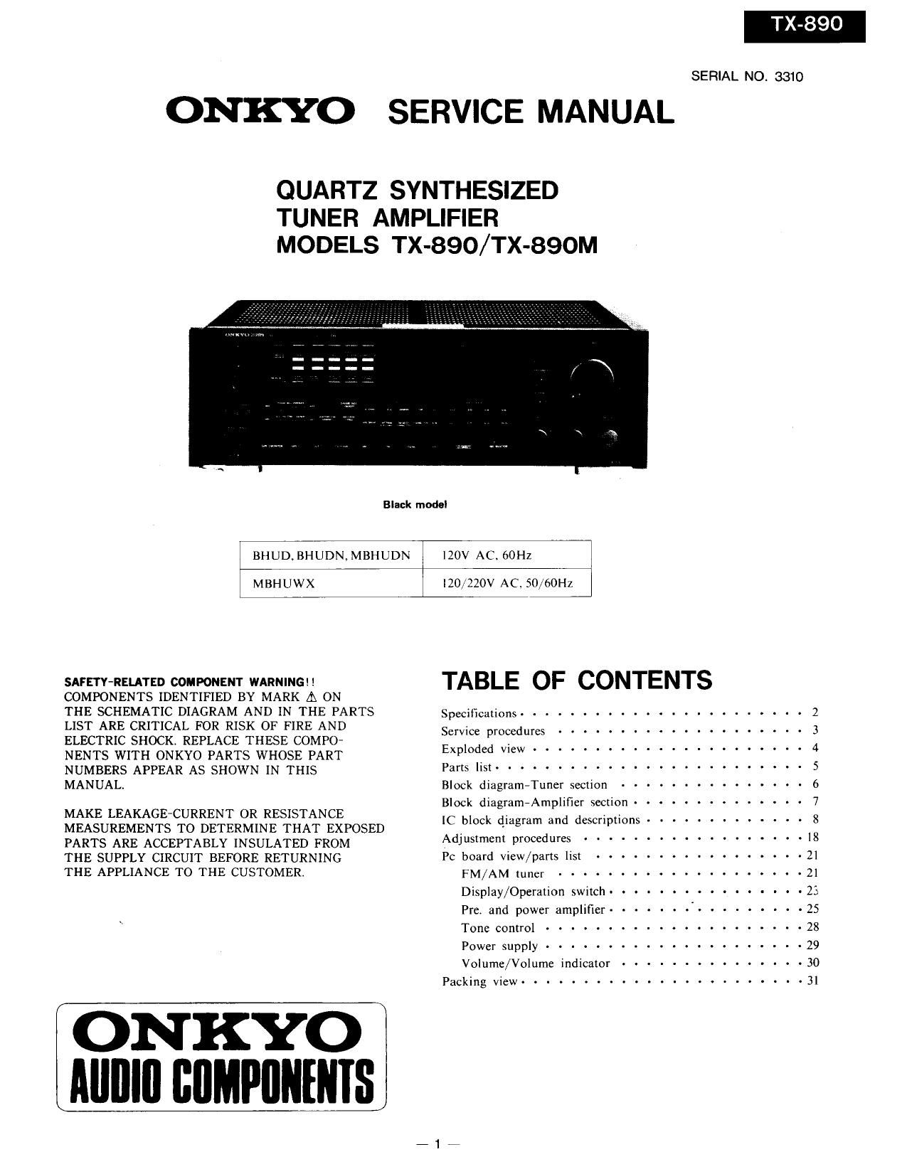
Onkyo TX 890 Service Manual

This is the 31 pages manual for Onkyo TX 890 Service Manual.
Read or download the pdf for free. If you want to contribute, please mail your pdfs to info@audioservicemanuals.com.

Page: 1 / 31
left right
Onkyo TX 890 Service Manual

Extracted text from Onkyo TX 890 Service Manual (Ocr-read)


Page 1

SERIAL NO. 3310

ONKYO SERVICE MANUAL

QUARTZ SYNTHESIZED
TUNER AMPLIFIER
MODELS TX-890/TX-890M

Black model

BHUD, BHUDNI MBIIUDN IZOV AC~ GOHZ I

MBHUWX I20/220V AC, 50,,60Hz I

SAFETYRELATED COMPONENT WARNING TABLE OF CONTENTS

COMPONENTS IDENTIFIED BY MARK A ON
THE SCHEMATIC DIAGRAM AND IN THE PARTS Specifications ....................... 2
LIST ARE CRITICAL FOR RISK OF FIRE AND

Service procedures .................... 3
ELECTRIC SHOCK. REPLACE THESE COMPO- E 1 d d r, ................ 4
NENTS WITH ONKYO PARTS WHOSE PART "P 0 E W

NUMBERS APPEAR AS SHOWN IN THIS Pans us: ------------------------- 5

MANUAL. Block diagram-Tuner section --------------- 6

MAKE LEAKAGE CURRENT OR RESISTANCE Wk diagramAmplmer mm) """"""" 7

- V ' ~ ............. 3

MEASUREMENTS To DETERMINE THAT EXPOSED [C IIGCI 445 d descrpm 8
PARTS ARE ACCEPTABLY INSULATED FROM Adjustment proceduref ------------------

THE SUPPLY CIRCUIT BEFORE RETURNING Pc board view/parts 11st ----------------- 21

THE APPLIANCE TO THE CUSTOMER. FM/AM me, .................... 21

Display/Operation switch ------- ~ : - . - - . '23

Prc. and power amplifier ------- . --------- 25

\ Tone control ..................... 25

Power supply ..................... 29

Volume/Volume indicator --------------- 30

Packing View ....................... 3]

ON KYO
Alllllll BflMPIIIIIIIIS

Page 15

TX-890

LC6527C-3802 (CODE CHAN GER)

0708
Buffer
U701 0754
Transmitter 2/ pmamp 333d EIUNSE
Infrared 6P1 U501 changer)
Rc-ilss
RC-AVQOM
X752
Ceramic oscillator
5; fi
l-osci n E] 05c;
}-rEst u 2] PD: -. POWER (Not used)
Vss [I E PD: -. PLAYER
T-RES E PD' _._. VOL UP To amp. circuit
(Groundmusrom -->PAa a 3) PDn -. VOL DOWN
STAND lav-4PM a E pm _. VOL 1ND (Not used)
man: 3] Pcz-- WE
(from mlcrupvooessor)SVSTEM IN-oPA: n E PC! -. mime
+Bt+5v)--vue a E PCo-> m
Connection diagram
Terminal No. Symbol Terminal Description

1 OSCl OSC Connect to the 4MHZ ceramic oscillator,

18 OSCZ

2 TEST TEST Test terminal. Connect to the ground,

3 Vss GND Ground terminal.

4 RES R_E-S Reset terminal.

5 PAO CUSTOM The custom code for decode is selected at this terminal. For this
model, the level is low.

6 PA] STANDBY Terminal for STANDBY detection, During low input, only the
POWER code is decoded.

7 PA2 REMOTE IN Signal input terminal from remote control preamp. Active low.

8 PA3 SYSTEM IN System code input terminal. Active high.

9 VDD +B(5V) Power supply terminal,

10 PCO SYSTEM OUT Output at this terminal are the custom code remote control code input
to REMOTE IN, the system code that has been converted correspond-
ing to the decoded data code.

ll PCl WI SENS Phono detection input terminal. Active low.

|2 PC2 RECEIVE This is the display output for remote control reception. Output is low
when decoded code is being received.

13 PC3 VOLIW During output of VOLUME UP/DOWN, a pulse (m; T:250ms)
is output.

[4 PDO VOL' DOWN When the volume DOWN code is input, a high pulse of lZOms is
output.

[5 PD] VOL UP When the volume UP code is input, a high pulse of l20ms is output.

[6 PD2 PLAYER Player control output terminal.

[7 PD3 POWER The power code input inverts the L/H. Level is high for power
being turned 0N.

_15__