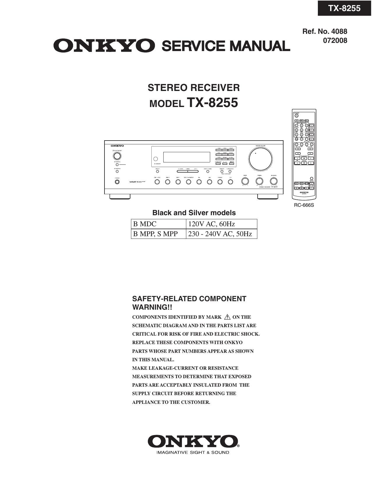
Onkyo TX 8255 Service Manual

This is the 66 pages manual for Onkyo TX 8255 Service Manual.
Read or download the pdf for free. If you want to contribute, please mail your pdfs to info@audioservicemanuals.com.

Page: 1 / 66
left right
Onkyo TX 8255 Service Manual

Extracted text from Onkyo TX 8255 Service Manual (Ocr-read)


Page 1

TX-8255

Ref. No. 4088

ONKYO SERVICE MANUAL 2"

STEREO RECEIVER
MODEL TX-8255

l% l%

RC-SBGS

Black and Silver models

B MDC 120V AC, 60Hz
B MPP, S MPP 230 - 240V AC, 50Hz

SAFETY-RELATED COMPONENT
WA R N I N G ! !

COMPONENTS IDENTIFIED BY MARK A ON THE
SCHEMATIC DIAGRAM AND IN THE PARTS LIST ARE
CRITICAL FOR RISK OF FIRE AND ELECTRIC SHOCK.
REPLACE THESE COMPONENTS WITH ONKYO
PARTS WHOSE PART NUMBERS APPEAR AS SHOWN
IN THIS MANUAL.

MAKE LEAKAGE-CURRENT OR RESISTANCE
MEASUREMENTS TO DETERMINE THAT EXPOSED
PARTS ARE ACCEPTABLY INSULATED FROM THE
SUPPLY CIRCUIT BEFORE RETURNING THE
APPLIANCE TO THE CUSTOMER.

ONKYO®

IMAGINATIVE SIGHT & SOUND

Page 14

A |

TX-8255

SCHEMATIC DIAGRAMS-3
DISPLAY SECTION

NAD_IS'887_7J m ~ THE COMPONENTS IDENTIFIED av MAHKA ARE CRITICAL FOR SAEErv
DISPLAY PC BOARD REPLACE ONLV WITH PART NUMBER SPECIFIED.
I I ~ VOLTAGE IMEASURED WITH VOLTMETERI |:|IS DC VOLTAGE (NO INPUT SIGNALI.
0852 ~ ALL PNP TRANSISTORS ARE EQUIVALENT TO 2SAIoI5-GR UNLESS OTHERWISE NOTED
G-ET-ZBGNK . ALL NPN TRANSISTORS ARE EQUIVALENT TO 2SCIBI s-GR UNLESS OTHERWISE NOTED.
7 31 F'- TUEE ~ ALL DIODES ARE EQUIVALENT TO ISSISa UNLESS OTHERWISE NOTED
I w u I ~ ELECTROLVTIC CAPACITORS( .a. IARE IN uF/WV.
T N ~ ALL CAPACITORS ARE IN pF/SOWV UNLESS OTHERWISE NOTED,
EX) 030- apE 330- sapE 331- saopE 333- 0.033UF
~ ALL RESISTORS ARE IN OHMS I/AWATTS UNLESS OTHERWISE NOTED.
. . - THE THICK LINES ON PC BOARD ARE THE PRINTING SIDE OF THE PARTS.
EX) PRINTING SIDE
~ CIRCUIT IS SUBJECT TO CHANGE FOR IMPROVEMENT

' ' Nc = NO mm m pans.
1-; 50-2 : xv
5 LOCalIOn oI connected IeImInaI m schemauc dIagramS.
7' AMPLIFIER PCB SD.z = SchemaIIc dIagrams-Z. x = A [O H v = I m 5.
' I gI TO NAAF-8886
3 W (gg-k S D-1 : D5
gig g am
I §T§ E
g - _ - _ - _ - _ - _ - -
:3; w «.av .qus 2. m
I g1g Mum o E
52 T .sv .EVCRU °
' fiwwmg I I_L,2n°
: DIGIuSEGsa NEW 0
D 7 sEazs
56 0551 25
$ch; 2:: o
- 52312;" 3:33 22 g mmmssomn
3ng 52522 g; 0 To NADG-8876
mm sEmz Is 5am .
3m 22 DIG. 522mm 5m :5 a 30-2 . E5
0
I 5 o
0
gal o
A I g 2
' = 2% III 3
~ IRour I .
[E
{2550 mu " '3
m m 9% g g
I (2552 IDIJ 3 ,7 I
can mu 3 E
j m
«2
I I
' Rg 5 R577 R573 H§5I Kw Ha I '
E m g 1 an: l m E l m gfil 42K 1 22K
E L' 2° .23 E 5
I E II °§3II 3I 33% EM T
I V! m I
R855 R555 R357 R555 H359 R550
a 1 $0 l 470 x l 560 l 5'50 1 I K 1 2 EK l
- N A «o - v
I.) u I. ... s
. geéIT ER], 23% EEIT 2§IT mi T .
L
mg Rm R565 R365 R366 m7
1 50 x 410 55a in I K 2 K
\I 3 E; 23 G 3 2
I am EEDI 23% god 3% Egg I
x2 g
I I E? I 3 I *5 T 3 I I
H869 Rm R571 H572 am am
I 8 l 520 L l no _ l m 1 .222 g 1 I2: 2 2K I
up n i P F:
5% :mi EMT rad? 5% ,ng T J

9928 XJ.

Page 32

SERVICE PROCEDURE

1. Replacing the fuses

EE This symbol located near the fuse indicates that the
fuse used is show operating type, For continued protection against
fire hazard, replace with same type fuse, For fuse rating, refer to
the marking adjacent to the symboll

EE Ce symbole indique que le fusible utilise est e lent.

Pour une protection permanente, n'utiliser que des fusibles de meme
typel Ce demier est indique la qu le present symbol est apposre.

REF NO. PART NAME DESCRIPTION PART NO. REMARKS
F901 FUSE 5A-UL/T-233 25232GGR !,
F901 or FUSE SA-T/UL-STZ 2522SSGR l,
F902 FUSE ZTSA-SE-EAK FUSE 25207SGR !,
F902 or FUSE ZTSA-SE-TL250V 25227SGR !,
F903 FUSE 5A-UL/T-233 252326612 1,
F903 or FUSE SA-T/UL-STZ 2522586R !,
F903 FUSE 215A-SE-EAK FUSE 25207SGR !,
F903 or FUSE ZTSA-SE-TL250V 25227SGR l,

: Canadian model
: European model

2. Safety check out
(U.S1Al model only)
After correcting the original service problem, perform the following safety check before releasing the unit to the customerl
Leakage current Check
Measure the leakage current to a known earth ground (water pipe or conduct etc) by connecting a leakage current
tester between the earth ground and exposed metal parts of the unit (input/output ground terminals, screw heads or metal overlays etc.).
Plug the power supply cord directly into a 120Vac 601-12 wall socket and tum ON/STANDBY button on
Any current measured must not exceed 015mA1

3. Memory Backup
The receiver uses a battery-less memory backup system in order to retain radio presets and other settings when its unplugged or in the
case of a power failure Although no batteries are required, the receiver must be plugged into an AC outlet in order to charge the backup
system Once it has been charged, the receiver will retain the settings for several weeks, although this depends on the environment and
will be shorter in humid climates

4. To initialize the unit
11 Press and hold down LINE 2 button, then press ON/STANDBY button when the unit is powered on.
21 After " Clear " is displayed, the preset memory and each mode stored in the memory, are initialized and
will return to the factory settings.

5. To check version of Main microprocessor
11 Press and hold down DISPLAY button, then press ON/STANDBY button when the unit is power on.
The main microprocessor version will be displayed on Front Display for about 3 seconds

Ver. 1.02/06 Y28A -

Version of Main microprocessor FW (Q601)

21 Press ON/STANDBY button to power off

6. Setting position before shipment

(1) MASTER VOLUME :MIN
(2) BASS : CENTER
(3) TREBLE : CENTER

(4) BALANCE : CENTER