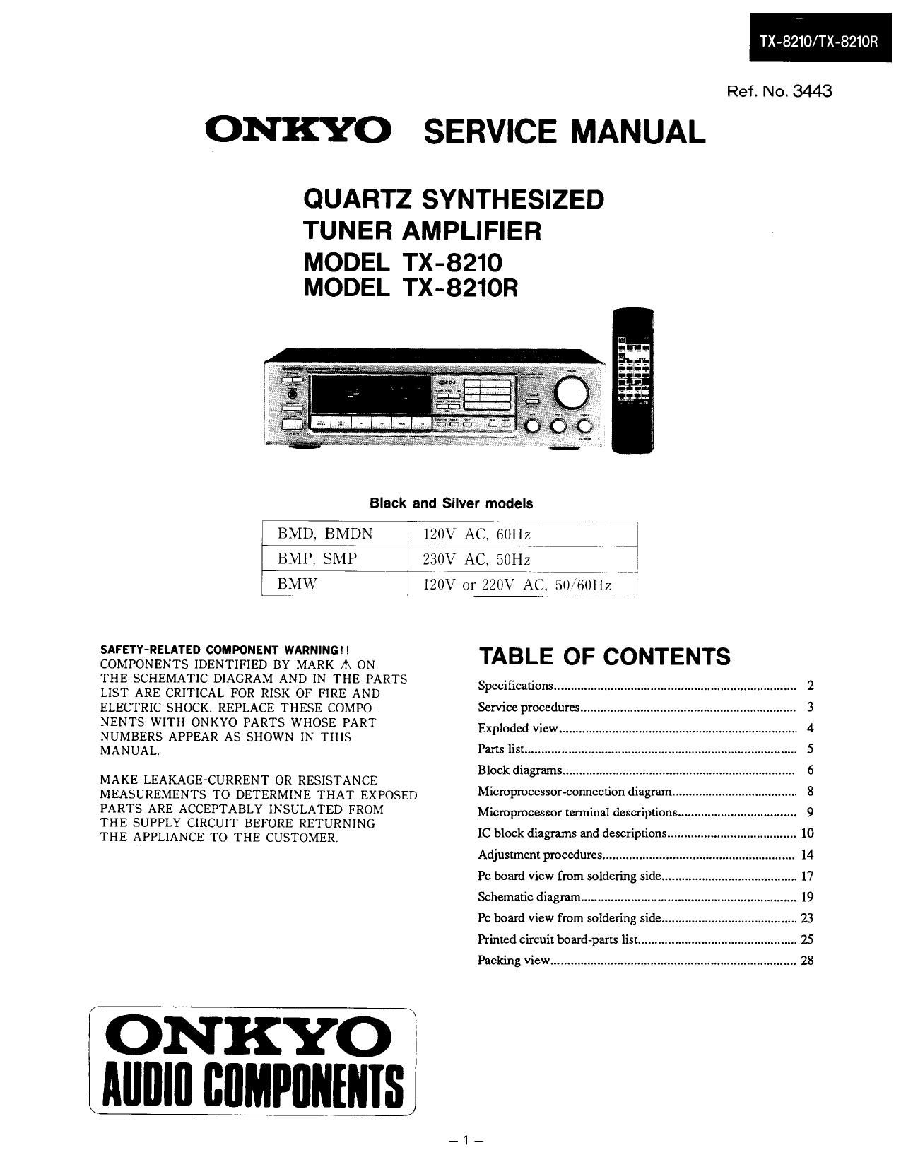
Onkyo TX 8210 R Service Manual

This is the 24 pages manual for Onkyo TX 8210 R Service Manual.
Read or download the pdf for free. If you want to contribute, please mail your pdfs to info@audioservicemanuals.com.

Page: 1 / 24
left right
Onkyo TX 8210 R Service Manual

Extracted text from Onkyo TX 8210 R Service Manual (Ocr-read)


Page 1

TX-8210/TX»8210R

Ref. No. 3443

ONKYO SERVICE MANUAL

QUARTZ SYNTH ESIZED
TUNER AMPLIFIER

MODEL TX-8210
MODEL TX-821OR

Black and Silver models

BMD, BMDN izov AC, 60142
BMP, SMP 230V AC, SOHZ
iBMW 120V 01: 220V AC ,0 60Hz J

SAFETY-RELATED COMPONENT WARNING! !
COMPONENTS IDENTIFIED BY MARK A ON
THE SCHEMATIC DIAGRAM AND IN THE PARTS
LIST ARE CRITICAL FOR RISK OF FIRE AND
ELECTRIC SHOCK. REPLACE THESE COMPO~
NENTS WITH ONKYO PARTS WHOSE PART
NUMBERS APPEAR AS SHOWN IN THIS
MANUAL.

MAKE LEAKAGEsCURRENT 0R RESISTANCE
MEASUREMENTS TO DETERMINE THAT EXPOSED
PARTS ARE ACCEPTABLY INSULATED FROM

THE SUPPLY CIRCUIT BEFORE RETURNING

THE APPLIANCE TO THE CUSTOMER

ONKYO
Llama cumpnums

TABLE OF CONTENTS

Specificalions........

Service procedures
Exploded view..
Parts list ........


Block diagrams .....
Microprocessor-connection diagram.
Microprocessor terminal descriptions
IC block diagrams and descriptions
Adjustment procedures ..................
Pc board View from soldering side
Schematic diagram ........................
PC board View from soldering side

Printed circuit board-parts list .......
Packing View 28

Page 14

TX-8210/TX-8210R

ADJUSTMENT PROCEDURES

Preparation
1. Input 3. Standard Knob Positions
FM mono: lkHZ. 75kHZ devi., GOdB/IJ V Master Volume Control ........................
FM stereo: lkflz, 67.5kI-Iz devi., 60dB/lz V Bass Control
Pilot signal 19kHz 7.5kHz devi. Treble Control ..
AM: 400142, 30% mod. Balance Control ..............
2. Outputs Input selector

Tape 2 Monitor.
Muting ......
Loudness
Speaker A.. .
Speaker B ................................................................ OFF

Connect the non-inductive type resistor of 8 ohms
to the all speaker terminals unless otherwise noted.

Idling Current Adjustment
Connect the DC voltmeter to the terminals P501,
and P502 (Vcr and IID) on the main circuit pc board.
Adjust the trim resistors R501 and R502 so that
the indicator of voltmeter becomes4 :i: 0.5mV.
NOIEzAdjust after switching on for 5 minutes.

Set Volume knob to the minimum position.

-14,