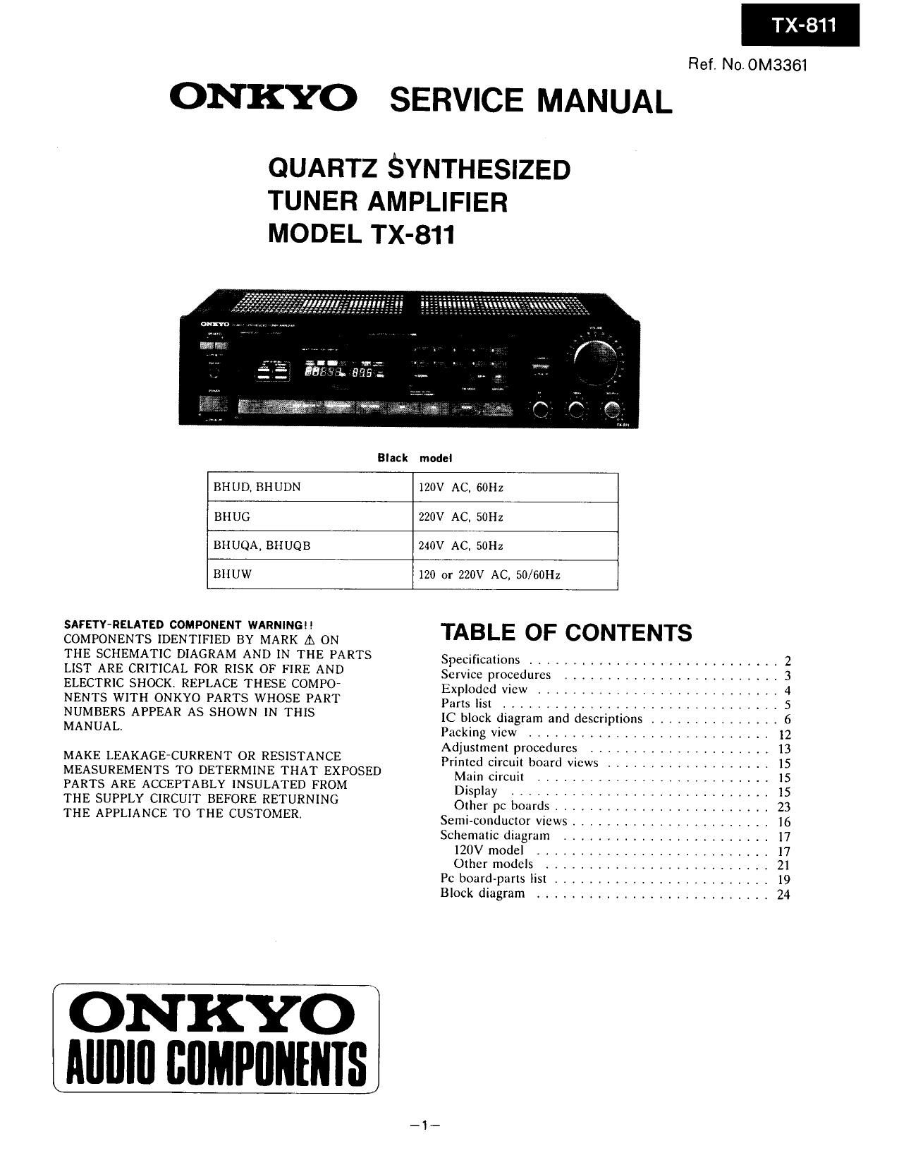
Onkyo TX 811 Service Manual

This is the 20 pages manual for Onkyo TX 811 Service Manual.
Read or download the pdf for free. If you want to contribute, please mail your pdfs to info@audioservicemanuals.com.

Page: 1 / 20
left right
Onkyo TX 811 Service Manual

Extracted text from Onkyo TX 811 Service Manual (Ocr-read)


Page 1

Ref. No. OM3361

ONKYO SERVICE MANUAL

QUARTZ SYNTHESIZED
TUNER AMPLIFIER

MODEL TX-

811

Black

model

BHUD. BH UDN

120V AC, 60Hz

BH UG

220V AC, 50Hz

BIIUQA, BHUQB

240V AC, 50Hz

BIIUW

120 or 220V AC. 50/60Hz

SAFETY>RELATED COMPONENT WARNING
COMPONENTS IDENTIFIED BY MARK A ON
THE SCHEMATIC DIAGRAM AND IN THE PARTS
LIST ARE CRITICAL FOR RISK OF FIRE AND
ELECTRIC SHOCK. REPLACE THESE COMPO
NENTS WITH ONKYO PARTS WHOSE PART
NUMBERS APPEAR AS SHOWN IN THIS
MANUAL.

MAKE LEAKAGE-CURRENT OR RESISTANCE
MEASUREMENTS TO DETERMINE THAT EXPOSED
PARTS ARE ACCEPTABLY INSULATED FROM

THE SUPPLY CIRCUIT BEFORE RETURNING

THE APPLIANCE TO THE CUSTOMER.

ON KYO
IIIIIIIII BIIMPIIIIIIIIS

TABLE OF CONTENTS

Specifications ............................. 2
Service procedures ......................... 3
Exploded vicw ............................ 4
Parts list ................................ 5
IC block diagram and descriptions ............... 6
Packing view ............................ 12
Adjustment procedures ..................... 13
Printed Circuit board vtcws ................... 15

Main circuit .......................... 15

Display .............................. 15

Other pc boards ......................... 23
Semi-conductor views ....................... I6
Schematic diagram ........................ 17

120V model ........................... 17

Other models .......................... 21
Pc board~parts list ......................... 19
Block diagram ........................... 24

Page 2

TX-811

EXPLODED VIEW

Page 7

0107

LM7001 (PLL synthesizer and controller)


6 Phase Detector
We 0-4
E charge Pump P02
XlN
xour
FMl VDDl


Programable Divider

Shift Register - Latch

ilél
%:%.


CE C L DATA

Pin No. Terminal Description

1 XOUT
Connect to the 7.2 MHz crystal oscillator.

2 XlN

3 CE Chip enable terminal. Connect to the PLL terminal of micro processor.

4 CL Serial clock input terminal. Connect to the CLOCK terminal of microprocessor,

5 DATA Serial data input terminal. Connect to the DATA terminal of microprocessor,

6 SYN Not used.

7 1301 Not used.

8 B02 FM control signal output terminal. L when FM.

9 BO3 AM control signal output terminal. L when AM,

10 AMIN AM local oscillator input terminal.

1] FMlN FM local oscillator terminal.

12 VDD 1 Power supply terminal for backup.

13 VDD2 Power supply terminal.

14 PDl Charge pump output of the phase detector which constitutes the PLL. High level is output when the
divided local oscillator frequency is high than the reference frequency.

15 PD2 In the opposite case, low level is output. Floating occurs when the frequencies matched.
The output is applied to the variable capacitor diode in the local oscillator through the low pass
filters.

16 Vss Ground terminal.