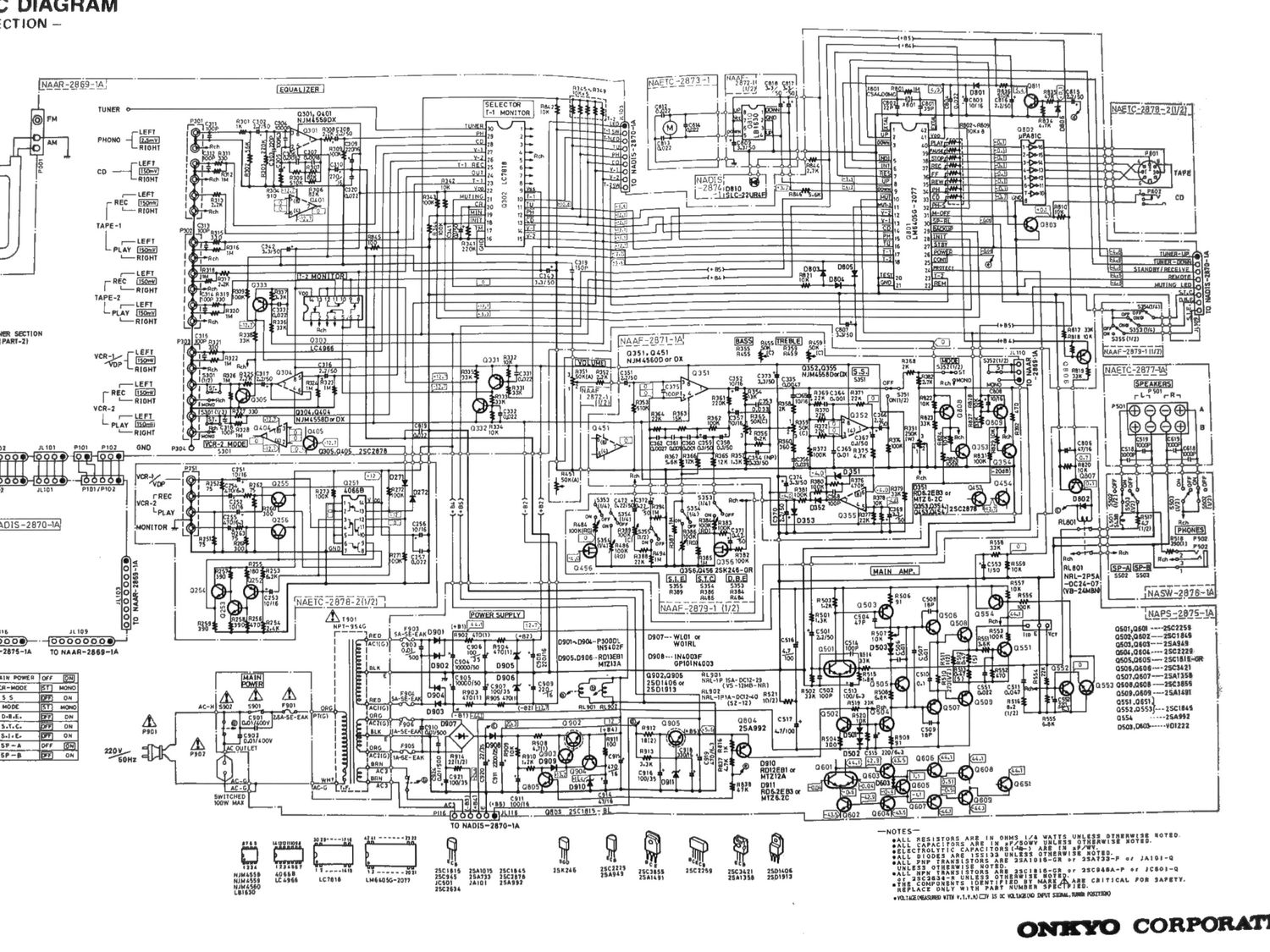
Onkyo TX 7440 Schematic

This is the 2 pages manual for Onkyo TX 7440 Schematic.
Read or download the pdf for free. If you want to contribute, please mail your pdfs to info@audioservicemanuals.com.

Page: 1 / 2
left right
Onkyo TX 7440 Schematic

Extracted text from Onkyo TX 7440 Schematic (Ocr-read)


Page 2

ADJUSTMENT PROCEDURES

P aration
. rm... 0 Standard knob position

TAPE .................
FM mono: lkHz, 75kHz devi., 60dB/pV VOLUfigNITOR _ . ' ' :IOURCE
FM stereo: lkHz, L+R 67.5kHz devi.: Pilot signal l9kHz BASS/TRBBLE/BALANCE .......... egg

7 .SkHz devi. """

MODE ..........................
AM: 400112, 30% mod 0 SPEAKER .................. :TEREO
0 Output ' . V SIMULATED STEREO ............... on:
Connect the non-inductive type resistor of 8 ohms to the DYNAMIC BASS EXPANDER .......... OFF
speaker terminal A of left and right channels unless other- STEREO IMAGE EXPANDER .......... OFF
Wise noted. SELECTIVE TONE CONTROL ......... 01:1:

Amplifier section

1 . Idling current adjustment

C onnect the DC voltmeter to the terminals [ID and VCT on
the power amplifier pc board.

Adjust the semi-fixed resistors R507 and R607 so that the

indication of voltmeter is 7.5 i 1.5mV.
Notes: VOLUME ............ Maximum, Open load,

Adjust after switching on for 5 minutes.

R607

/-J' O ON

F.
o o o P 9
_ n I _ a
a $ _ 5 2 u g
-' CI DD 4; U DC
l0 V
E s s
3 IA. IL
m
k
Power amplifier pc board \
F902

Db

FSOI

Pit

5905
F906

Second

dfl_