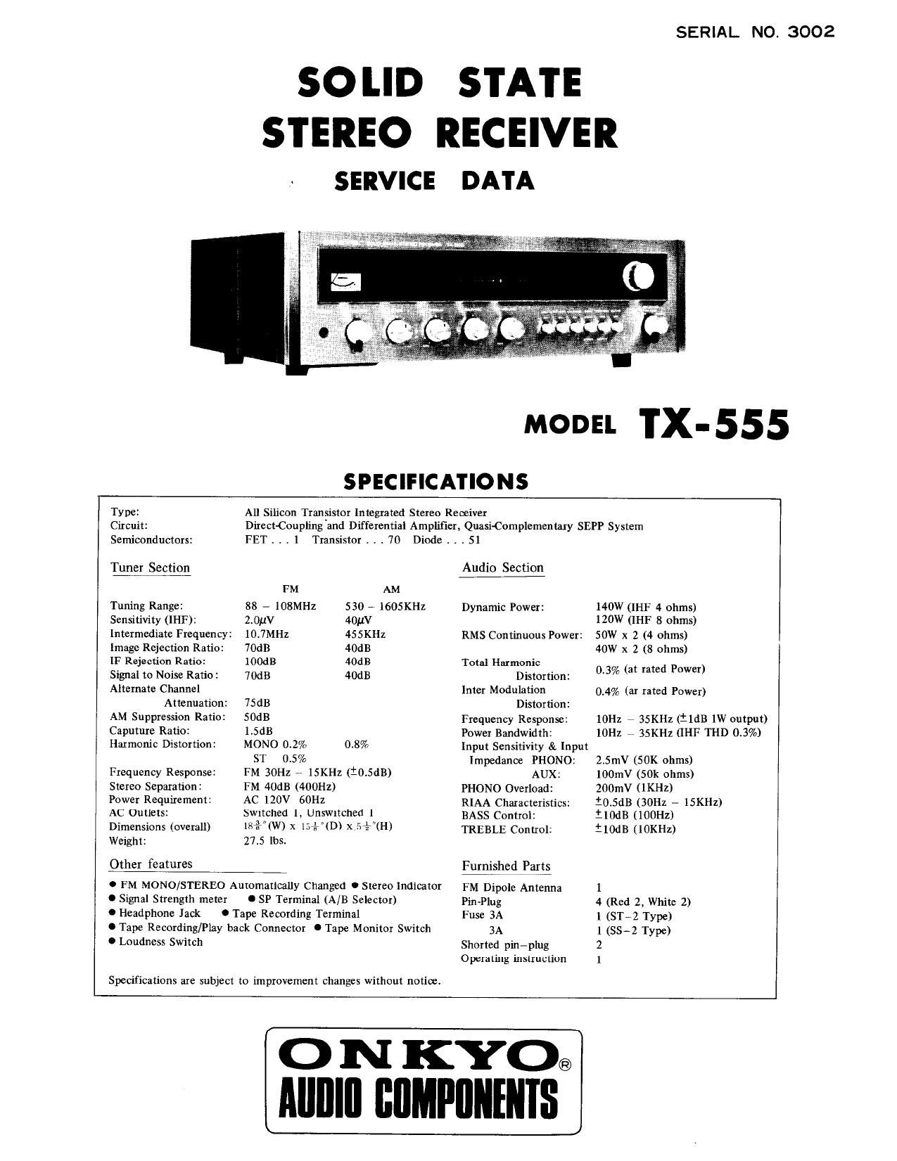
Onkyo TX 555 Service Manual

This is the 10 pages manual for Onkyo TX 555 Service Manual.
Read or download the pdf for free. If you want to contribute, please mail your pdfs to info@audioservicemanuals.com.

Page: 1 / 10
left right
Onkyo TX 555 Service Manual

Extracted text from Onkyo TX 555 Service Manual (Ocr-read)


Page 1

SERIAL NO. 3002

SO |.|D STATE
STEREO RECEIVER

SERVICE DATA

MODEL TX-555

SPECIFICATIONS

Type: All Silicon Transistor Integrated Stereo Remiver
Circuit: DirectCoupling "and Differential Amplifier, QuasiComplementary SEPP System
Semiconductors: FET . . . l Transistor . . . 70 Diode . t , 51
Tunerfltion Audio Section
FM AM
Tuning Range: 88 7 108MHz 530 -- 1605KHZ Dynamic Power: 140W (IHF 4 ohms)
Sensitivity (II-IF): 2.0;1V 40HV 120W (II-IF 8 ohms)
Intermediate Frequency: 10.7Ml-lz 4SSKH2 RMS Continuous Power: 50W x 2 (4 ohms)
Image Rejection Ratio: 70dB 40:13 40W x 2 (8 ohms)
IF Rejection Ratio: iOOdB 40:13 Total Harmonic
Signal to Noise Ratio: 70dB 40dB Distortion: 03% (at rated Power)
Alternate Channel Inter Modulation 0.4% (ar rated Power)
Attenuation: 7SdB Distortion:

AM Suppression Rafio: SOdB Frequency Response: 10H: , 35KHz (ildB 1W output)
Caputure Ratio: 1.5dB Power Bandwidth: lOHz , 35KHz (IHF THD 0.3%)
Harmonic Distortion: MONO 0.2% 0.8% Input Sensitivity 8:. Input

ST 0.5% Impedance PHONO: 2.5mV (50K ohms)

Frequency Response:
Stereo Separation:
Power Requirement:
AC Outlets:
Dimensions (overall)
Weight:

Other features

FM EOHZ -- lSKHZ (:045dB)
FM 40dB (400Hz)

AC 120V 60Hz

Swrtched l, Unswrtched I
18%"{W) x 1.315. (D) x 57TH)
27.5 lbs

0 FM MONO/STEREO Automatically Changed 0 Stereo Indicator

AUX:
PHONO Overload:
RIAA Characteristics:
BASS Control:
TREBLE Control:

Furnished Parts

lOOmV (50k ohms)
200mV (1KHz)

10.5dB (Will 7 ISKHZ)
ilOdB (100HZ)

t lodB (lOKHz)

FM Dipole Antenna 1
0 Signal Strength meter 0 SP Terminal (A/B Selector) Pin-Plug 4 (Red 2, White 2)
O Headphone Jack 0 Tape Recording Terminal Fuse 3A 1 (STVZ Type)
0 Tape Recording/Play back Connector 0 Tape Monitor Switch 3A 1 (SSAZ Type)
O Loudness Switch shorted piniplug 2

Specifications are subject to improvement changes without notice.

0 porating in struction

l

O N KYO®
AIIIIIII IIIIMPIIIIIIIIS

Page 2

COMPONENT lOCA'I'IONS

ILLUS.

ILLUS.

NO. DESCRIPTION NO. DESCRIPTION
1 End Cap 8 Push Switch
2 From Panel 9 Knob-Tuning
3 Glass Plate 10 Decoration Frame
4 Knob-SPK 11 FM Front End
5 Knob-Tone (S) 12 Upper Panel
6 Knob-Tone (L) 13 Washer
7 Knob-Volume l4 Screw-Wood Case

Page 4

©®O©O® ® ®

®O®®QE®® ®

fig? DESCRIPTION fig? DESCRIPTION
1 Speaker/Power Switch 16 Headphone Jack
2 Bass Control 17 AM. FM Antenna Terminal
3 Treble Control 18 AM Coil Antenna
4 Balance Control 19 PHONO Terminal
5 Volume 20 AUX Terminal
6 Cut Filter (Low) 21 REC Terminal
7 Cut Filter (High) 22 PLAY Terminal
B Loudness Switch 23 REC/PB Terminal
9 Mode Switch 24 Speaker Terminal A
10 Tape Monitor Switch 25 Speaker Terminal B
11 FM Muting Switch 26 Fuse Holder
12 Selector Switch 27 AC70UTLET
l3 Tuning Knob 28 ACAOUTLET
[4 Stereo Indicator 29 Ground Terminal
15 Signal Indicator 30 AC Cord