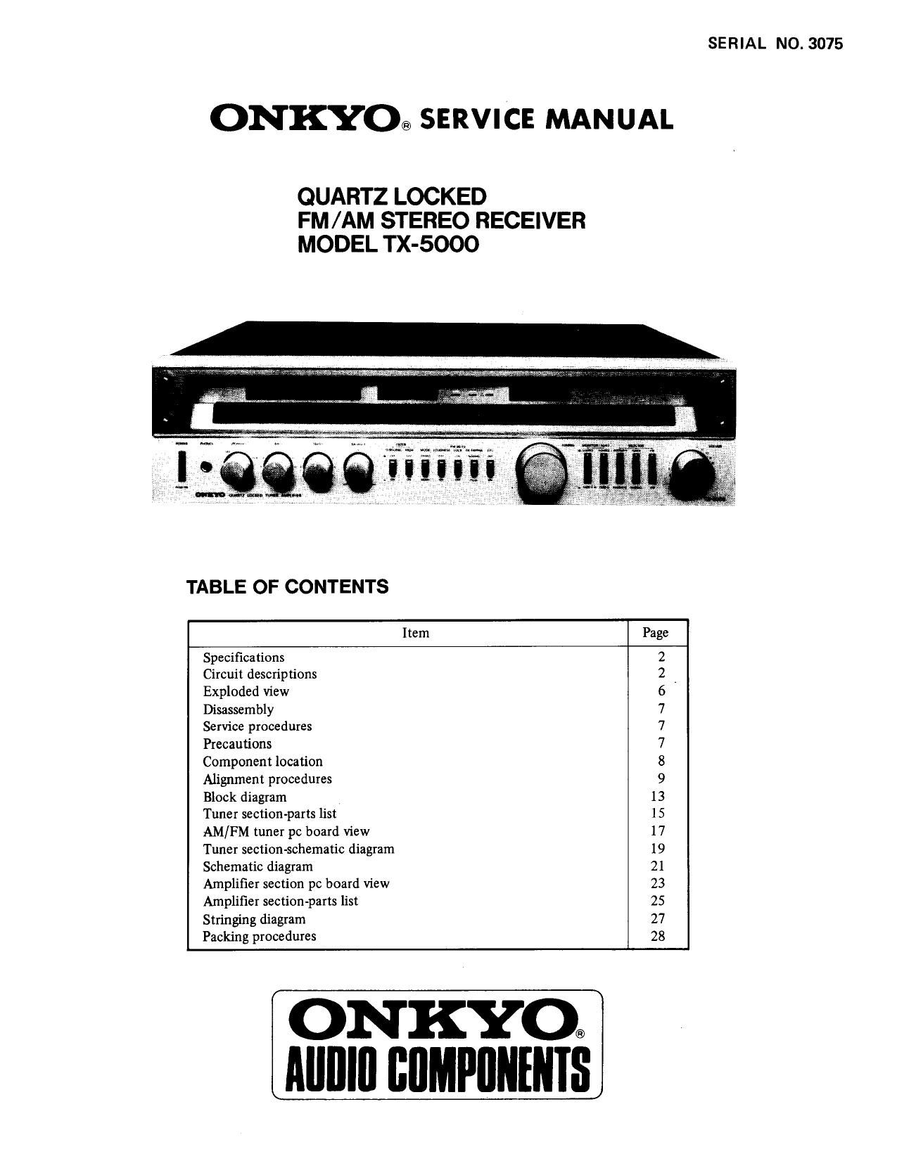
Onkyo TX 5000 Service Manual

This is the 21 pages manual for Onkyo TX 5000 Service Manual.
Read or download the pdf for free. If you want to contribute, please mail your pdfs to info@audioservicemanuals.com.

Page: 1 / 21
left right
Onkyo TX 5000 Service Manual

Extracted text from Onkyo TX 5000 Service Manual (Ocr-read)


Page 1

SERIAL NO. 3075

ONKYO® SERVICE MANUAL

QUARTZ LOCKED
FM/AM STEREO RECEIVER
MODEL TX-5000

TABLE OF CONTENTS

Item Page
Specifications 2
Circuit descriptions 2
Exploded view 6
Disassembly 7
Service procedures 7
Precautions 7
Component location 8
Alignment procedures 9
Block diagram . l3
Tuner section-parts list 15
AM/FM tuner pc board View 17
Tuner section-schematic diagram 19
Schematic diagram 21
Amplifier section pc board View 23
Amplifier section-parts list 25
Stringing diagram 27
Packing procedures 28

ON KYO®
Alllllll BflMPflNleS

Page 2

SPECIFICATIONS

AMPLIFIER SECTION

Output Power:

Total Harmonic
Distortion:

IM Distortion:
Damping Factor:
Frequency Response:
RIAA Deviation:
Sensitivity 8t
Impedance:

Phono Overload:

Signal-to-Noise Ratio:

Residual Hum &Noise:
Tone Controls:
Filters:

Loudness (-40 dB):

TUNER SECTION
FM:

Tuning Range:
Usable Sensitivity:

50 dB Quieting
Sansitivity:

Capture Ratio:

Image Rejection
Ratio:

IF Rejection Ratio:

65 watts per channel, min. RMS,
at 8 ohms both channels driven,
from 20 Hz to 20,000 Hz, with no
more than 0.03% total harmonic
distortion.

0.03% at rated power
0.028% at 1 watt output
0.03% at rated power
0.028% at 1watt output

50 at 8 ohms

15 Hz - 30,000 Hz (11 dB)
20 Hz - 20,000 Hz (10.5 dB)

Phono: 2.5 mV, 50 kohms
Tape Play: 150mV, 50 kohms
Tape Rec: 150 mV,3.S kohms (PH)
200 mV R.M.S. at 1 kHz,

0.03% T.H.D.

Phono: 76 dB (IHF A
weighted, 1 watt out-
put, 5 mV input)

86 dB (A" weighted,
10 mV input)

80 dB (IHF A
weighted, 1 watt out-
put 0.5 V input)

95 dB ("A" weighted)
0.8mV at Volume Control: min.
(A" weighted)

Tape: .

Bass: 112 dB at 100 Hz
Treble: :10 dB at 10 kHz
High: 6 kHz, 12 dB/oct.
Subsonic: 10 Hz, 12dB/oct.
+8 dB at 40 Hz

+5dB at 20 kHz

88 - 108 MHz

Mono: 10.3 dBf, 1.8pV
Stereo: 17.2 dBf. 4.0}1V
Mono: 14.7 dBf, 311V
Stereo: 37.2 dBf, 40uV
1.4 dB

90dB

100 dB

CIRCUIT DESCRIPTIONS

TUNER SECTION

Spurious Rejection
Ratio:
Signal-to-Noise Ratio:

Alternate Channel Att:
AM Suppression Ratio:
Harmonic Distortion:

Frequency Response:
Stereo Separation:

Subcarrier
Suppression:
Muting Level:
Stereo Threshold:
Ouartz Lock Level:

AM:

Tuning Rage:

Usable Sensitivity:

lmage Rejection
Ratio:

IF Rejection Ratio:

Signal-to-Noise Ratio:

Harmonic Distortion:

GENERAL

Power Supply:
Outputs:

Inputs:

Antennas:

Semiconductors:

Dimensions
(WxHxD):

Weight:

1/2 IF 90 dB
Mono: 73 dB
Stereo: 68 dB
70 dB

55 dB

Mono: 0.15%
Stereo: 0.3%

30 Hz - 15,000 Hz (115 dB)
40 dB at 1 kHz
33 dB at 100 Hz - 10,000 Hz

SOdB

17.2 dBf, 4 MV
17.2d8f, 451V .
17.2 dBf, 4 MV

525 - 1,620 kHz
25 uV

45 dB
40 dB
40 dB
0.8%

AC 120 volts, 60 Hz

Speaker A 8: B, Phones, Tape Rec
Out 1 8i 2, AC Outlet (x 2). EPS
OUT (PRE OUT)

Phono 1 8i 2, Tape Play 1 81 2,
EPS IN (MAN IN)

FM and AM Antennas

FM: 300 ohms balanced and
75 ohms unbalanced
AM: built-in ferrite core

antenna and external
terminal
2 FETs, 51 transistors, 16 le,
50 diodes, 1 fluorescent digital
display tube

540 x 146 x 400 mm
21-1/ " x 5-3/ x15-3/ "
15 kg, 33 lbs

Specifications and features are subject to change without

notice.

A major feature of the FM tuner section of the TX»5000 is the Quartz Locked system which detects any difference in fre-
quency between the IF signal and the reference signal generated by the crystal osillator.
Another important feature of this equipment is the Touch sensor circuit.

When the TUNING knob is touched by hand, the quartz locked circuit is deactivated, permitting the tuned frequency to be
freely varied just as in conventional equipment.

POWER AMPLIFIER SECTION
A major feature of the power amplifier section is the servo operational amplifier system.

Page 7

DISASSEMBLY

Top Cover

Remove the four screws (4) holding the top cover and side

bracket.

Remove the two screws (3) holding the top cover and back

panel.

Front Panel

Remove the top cover.

Remove the TUNING knob.

Remove the five screws holding the front panel and front

bracket.

Bottom board

Remove the four screws (24) holding the bottom board

and chassis.

Remove the four screws (25) holding the bottom board and

legs.

Meters

Remove the top panel.

Remove the two screws holding the lamp bracket and front

bracket.

Dial Glass

Remove the four screws holding the dial glass and front

panel.

Notes: The dial glass has been mounted by applying an 800
gr torque to the screws.
If the dial glass is removed during repairs, and a
torque driver is available, apply 800 gr torque to the
screws when replacing. If however, a torque driver
is not available, simply tighten the screws by hand.
When replacing the dial glass, insert all relevant
component parts (9-13) in accordance with the
exploded View.

Pointer [amp

Remove the top cover and front panel.

Replace the pointer assy.

PRECAUTIONS

Power Amplifier Transistors

Remove the top cover and bottom board.

Remove the two screws holding the chassis and radiator
from bottom side.

Remove the screw holding the radiator and radiator bracket
(R) from right side.

Remove a screw holding the radiator and radiator bracket
(L) from left side.

Tone control p.c.b.

Remove the top cover, bottom board and front panel.
Remove the three nuts on the Bass, Treble and Balance
volume shaft.

Remove the two screws holding the switch and front
bracket.

Remove the four screws holding the front bracket and
chassis from both sides.

SERVICE PROCEDURES

Sensor Switch (SENSOR)

This switch enables the quartz lock system for automatic
FM tuning to be matched with the various operating con»
ditions. Set it at LOW initially. Switch to NORM or HIGH
if the TUNED lamp does not instantly turn off when you
touch the tuning knob.

Power Meter/Signal Strength Meter

When the tuning is not being operated, this meter displays
the level of power applied to the right speaker system. The
instant the tuning knob is touched, the meter changes to
display the signal strength of the riado broadcast being
received at that moment. Tune a station so the needle
moves as far to the right as possible.

1. For continued protection against fire hazard, replace only with same type and same rating fuse.

AC fuse 5A (ST-6)

PARTS NO. 252050

2. Replacement for power, complementary and driver transistors, if necessary, must be made from the same beta (HFE) group

as the original type.

3. All CMOS devices have diode input protection against adverse electrical environments such as static discharge.

Unfortunately, there can be severe electrical environments during the process of handling. For example, static voltages

generated by a person walking across a common waxed floor have been measured in the 4 to 15 kV range (depending on

humidity, surface conditions, etc.). These static voltages are potentially disastrous when discharged into a CMOS input

considering the energy stored in the capacity (~ 300 pF) of the human body at these voltage levels.

Present CMOS gate protection structures can generally protect against 'overvoltages. This is usually sufficient except in

the servere cases. Following are some suggested handling procedures for CMOS devices, many of which apply to most

semiconductor devices.

1. All MOS devices should be stored or transported in materials that are somewhat conductive. MOS devices must not be
inserted into conventional plastic snow or plastic trays.

. All MOS devices should be placed on a grounded bench surface and operators should ground themselves prior to handing
devices, since a worker can be statically charged with respect to the bench surface.

. Nylon clothing should no be worn while handling MOS circuits.

. When lead straightening or hand soldering is necessary, provide ground straps for the apparatus used.

. Double check test equipment setup for proper polarity of voltage before conducting parametric of functional testing.

. All unused device inputs should be connected to VDD or V58.

_7_

to

mun-Aw

Page 21

|\»50llil

PACKING PROCEDURES

PACKING PROCEDURES - PARTS LIST

REF. NO. PARTS Nor

29340396
29358002
29365006
292064
29100006
2900084
29100038
29360362

mummawn-

DESCRIPTION

Instruction manual

Service station list

Warranty card

FM antenna

250x350mm, Poly bag
500x1,000mm, Protection sheet
720x950mm, Poly bag

Label

13

Fig. 40

REF. NO.

10
11
12
13
14

PARTS NO.

282301

29360363
29090482
29090483
29050335
260012

29355045

DESCRIPTION

Sealing hook
Caution label

Pad (R)

Pad (L)

Master carton box
W50xl 70mm, Tape
Sensor tag

ONKYO CORPORATION
International Division: No. 24 Mori Bldg., 23-5, 3-chome, Nishi-Shinbashi, Minatwku, Tokyo, Japan

Telex: 2423551 ONKYO J,

ONKYO U.S.A. CORPORATION

Eastern Office

42-07 20th Avenue, Long Island City, New York 11105, U.S. A.

Midwest Office
935 Sivert Drive, Wooddale, Illinois 60191, U.S.A.

Phone: 03432-6981

Phone: (312) 595-2970

ONKYO DEUTSCHLAND GMBH, ELECTRONICS

8034 Manchen-Germaring, lndustriestrasse 18, West Germany.

_2g,

Telex: 521726

Phone: (212) 7284639

Talafun: 391-811-5041

1804 Printed in Japan