Onkyo TX 4500 Service Manual

This is the 29 pages manual for Onkyo TX 4500 Service Manual.
Read or download the pdf for free. If you want to contribute, please mail your pdfs to info@audioservicemanuals.com.

Page: 1 / 29
left right
Onkyo TX 4500 Service Manual

Extracted text from Onkyo TX 4500 Service Manual (Ocr-read)


Page 1

thIAL No.3024

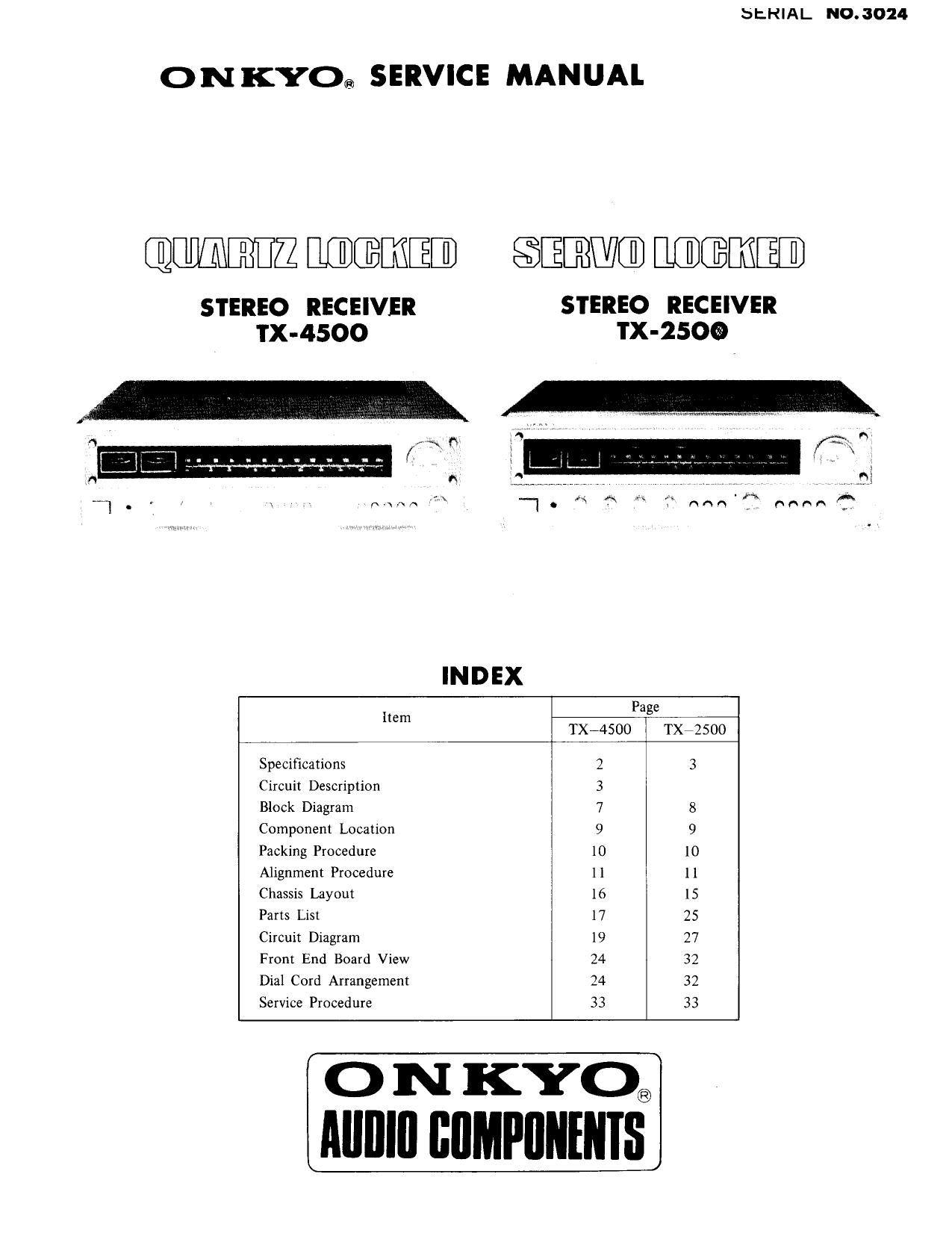
ONKYO® SERVICE MANUAL

QIIlIBIZ MEEEEi/i l1] 83 ENG] HERE [I]

STEREO RECEIVER STEREO RECEIVER
TX-4500 TX-ZSOQ

INDEX
Page
Item
TX-4500 TX72500

Specifications 2 3
Circuit Description 3

Block Diagram 7 8
Component Location 9 9
Packing Procedure 10 [0
Alignment Procedure 11 ll
Chassis Layout 16 [5
Parts List 17 25
Circuit Diagram 19 27
From End Board View 24 32
Dial Cord Arrangement 24 32
Service Procedure 33 33

O N [{XC)®
Alllllfl IIIIMPIINENIS

Page 6

5. The Explanation of Protection Circuit
1. Steady function

While the B voltage is supplied to the protection circuit as the power source switch is turned on, it is so designed
as to allow a lag of almost 4 seconds in the time required for the relay to be turned ON, by means of the time-constant
circuit set to motion by R 716 and 706 so that a drop in the output may be prevented of the main circuit in the
unsteady state.

In the steady state, transistors of Q 701 to Q 705 are cut off, so much so that the voltage at both ends ofC 706
is caused to register a value of 6 by the function of R 720 and D 709, causing the transistor of Q 706 and the delay
to be turned ON, bringing forth the output.

Again, D 709 is designed so as to keep both ends of the relay coil from being brought under the pressure of abnormal
voltage. In addition, IS 1554 between the base collectors for respective transistors is designed to thwart inverse
current.

2. Detection of abnormal voltage

As the equivalent of 2 or more is generated at the center line of the main amplifier, there is a mixing between the
right side and the left side at R 701 and 702, with the alternate current portion being cut off at C 701 and 702.
In the case that the direct current generated here is negative, the current, passing through D 701, is broken up into
partial pressure, acting on the base of the transistor at Q 702, which, in turn, causes Q 702 to open up allowing
the current to pass through in the sequence of D 706- R 707-- R 708.

As a result, the portion of voltage generated by R 708 is caused to be reinforced to Q 705, rendering the transistor
to be turned 0N. This, in turn, causes the voltage of the collector at Q 705 to fall, thus making the base potential
of Q 706 go deeper into the negative side and turning the Q 706 OFF. This in turn causes the relay to be turned
OFF, and also, the output circuit to be cut off.

in the event the base potential is on the positive side, the similar function takes place within the loop of Q 721
*D 202~R 707»R 708.

By eliminating a cause or causes for DC generation at the center line, the relay is caused to turn ON by the function
staged in reverse order of the description given, causing the proper function to start automatically.

3. Detection of abnormal current

When the abnormal current is generated on the driver stage (power stage) of the main amplifier, the voltage is detected
by the collector resistance and added subsequently to semi-solid resistance R 537 and 637 which are designed for
current detection in the protection circuit. (The semi-solid resistance is set to function with the adequate flow
of current causing the protection circuit to start operating. Refer to the Chapter dealing with Adjustment.) By
the voltage reaching Q 704 by way of D 536 and D 636, Q 704 is caused to be turned 0N while R 705 witnesses
a voltage drop, resulting in Q 703 being turned ON,

As a result, the current flows in the sequence of Q 703 --R 711 -D 707--R708, and by the voltage generated
at R 708, a 705 is turned ON while Q 706 is turned OFF, causing the relay, in turn, to be turned OFF, thereby
cutting off the output circuit. By the voltage added to the base of Q 704 through R 713, on the other hand,
Q 704 is turned ON and on account of this, the lock circuit is set to work by Q 704 and Q 703, causing the realy
to be kept in the OFF state.

in the event a large current flows into the transistor of the main circuit, the said circuit is caused to start functioning,
locking up the amplifier output in the OFF state. For this reason, it is necessary for the power source to be cut
off before setting out to remove the cause for abnormal current. Turning the power source back on will set off
the normal function. It should be noted that turning the lock circuit on immediately after the power source was
turned OFF will not lead to a spontaneous release of the lock-up, and therefore, it must be assured that the lock
circuit is turned ON a few seconds after the power source has been turned OFF,

Page 11

PACKING PROCEDURE

\ é Insert the Protection Sheet bet
I .351 Antenna and Rear Panel.

Accessory Bag Complete

ITEM DESCRIPTION

1 Instiuction Manual

2 Caution Cardiw

3 Warranty Card

4 Silicon Cloth

5 Fuse 3A(ST-72)
3A(SS-2)
4A(ST72)

6 Poly Bag SOXISO

7 FM Antenna Ass'y

8 Poly Bag 350x250

9 shorted Pin P0-107

10 Tag»Sensoy

11 Tag-Cabinet Composition

12 Sheet 500x1200

13 Poly Bag 720x1020

14 Adhesive Tape W30

15 Caution Card

16 Padiside (Left)

17 Pad-Side (Right)

18 Master Carton Box

19 Accessory Bag Complete (1-2. 4-8)

w§\

Real Panel
0

PHONOvl g gPHONO-Z

W,

TX -4500

STOCK NO.

29340125
29355036-1
293036-1
292017-2
NONE
NONE
252038
29100002
292064
29100006A
250153
29355039
29380004
290093
29100020
261504
293041
29090116A
29090115A
29050054
13829119

,102

Hp-A»_._..-

..

400m

H~H_._.

fig-9

TX-2500
STOCK NO.

29 340127
29355036-1
293036-1
292017 -2
25 2005

25 2006
NONE
29100002
292064
29100006A
25015 3

29 355039
29 380004
290093
29100020
261504

29 3041
290901 16A
290901 15A
29050060

QTY
1

Hp-__._.

HHHNHH.

4 0cm

._.._.._._.