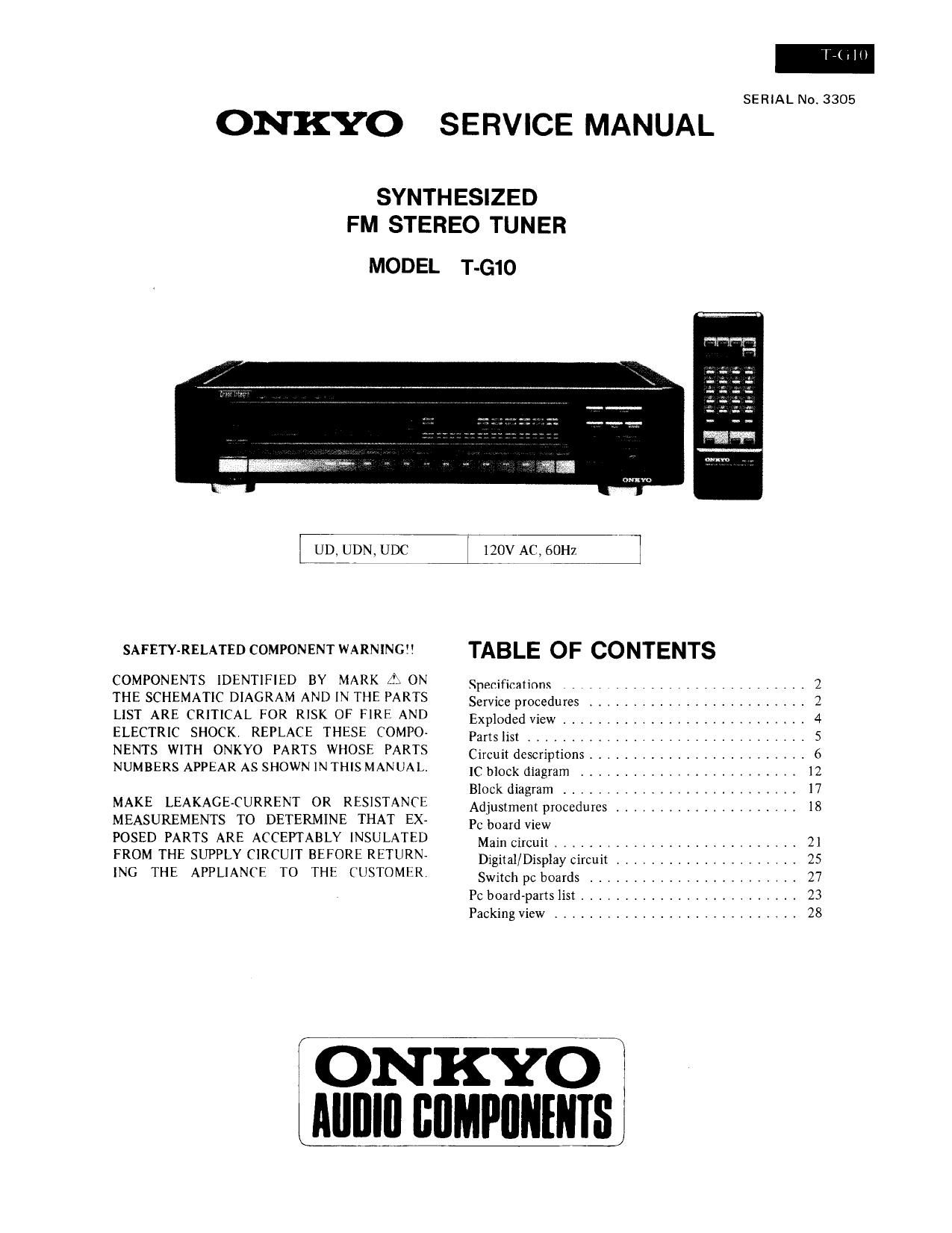
Onkyo TG 10 Service Manual

This is the 24 pages manual for Onkyo TG 10 Service Manual.
Read or download the pdf for free. If you want to contribute, please mail your pdfs to info@audioservicemanuals.com.

Page: 1 / 24
left right
Onkyo TG 10 Service Manual

Extracted text from Onkyo TG 10 Service Manual (Ocr-read)


Page 1

SERIAL Nos 3305

ONKYO SERVICE MANUAL

SYNTHESIZED
FM STEREO TUNER

MODEL T-G10

UD, UDN, UDC 120V AC, 60Hz

SAFETY-RELATED COMPONENT WARNING TABLE OF CONTENTS

COMPONENTS IDENTIFIED BY MARK {3; ON

Specifications ............................ 2
THE SCHEMATIC DIAGRAM AND IN THE PARTS Service procedures ______________________ 2
LIST ARE CRITICAL FOR RISK OF FIRI" AND Exploded View _____ 4
ELECTRIC SHOCK REPLACE THESE COMPO Pans liSI ................................ 5
NENTS WITH ONKYO PARTS WHOSE PARTS Circuit descriptions ......................... 6
NUMBERS APPEAR AS SHOWN IN THIS MANUAL. 1C bIock diagram ______________________ 2
Block diagram .......................... 17
MAKE LEAKAGE-CURRENT OR RESISTANCE Adjustment procedures _____________________ 18
MEASUREMENTS TO DETERMINE THAT EX- Pc board view
POSED PARTS ARE ACCEPTABLY INSULATED Main circuit 21
FROM THE SUPPLY CIRCUIT BEFORE RETURN Digital/DispIay circuiI . .................. 25
INC THE APPLIANCE TO THE CUSTOMER Switch pc boards ........................ 27
PC board-parts list ......................... 23
Packing view ............................ 28

I ON KYO
IIIIIIIII BIIMPIININIS

Page 2

SPECIFICATIONS

Tuning Range:

875 - 108r0MHz
(AUTO MODE SOkI-Iz steps,
MANUAL MODE 25kHz steps)

Usable Sensitivity: Mono: 0.8].LV (S/N 26GB, 40kHz
Dev) DIN
Stereo: 20.0w, (S/N 46dB,
40kI-[z Dev.) DIN
SOdB Quieting Sensitivity: Mono: 15.8dBf, l.7uV
Stereo: 37.2dBf, 20uV
Capture Ratio: 1.0dB
Image Rejection Ratio: lOOdB
IF Rejection Ratio: lOOdB
Signal-to-Noise Ratio: Mono: 95dB (ll-1F)
Stereo: 85dB (IHF)
Selectivity: 80dB (1 SOOkHz, IF: super
narrow)

SERVICE PROCEDURES

1. Replacing the lamp
This unit uses the lamp listed below.
Circuit no. Parts no. Desciption
0754 2|0064A PL 6.3V, ZSOmA, Dial
plate illumination

2. Safety-check out (D model)
After correcting the original service problem. perform
the following safety check before releasing the set to
the customer:
Connect the insulating-resistance tester between the
plug of power supply cable and tapping screw holding
the back panel and top cover.
Specification: 3.3MQ 110% at 500V

AM Suppression Ratio:

Total Harmonic Distortion:

Frequency Response:
Stereo Separation:

Output Voltage:
Dimensions (W X H X D):

Weight:

60dB
Mono: 0.009% (IF: wide)
Stereo: 0.02% (IF: wide)

30 7 15,000Hz (+0.5dB, 71.0w)
55dB at 1kHz (er wide)

33013 at 70 - 10,000Hz (IF: wide)
0 7 LSV

465 x 103 x 387mm

18-5/16" x 4-1/16" x 15-1/4
8.5kg, 18.7lbs.

Specifications and features are subject to change without notice.

. Memory Preservation

This unit does not require memory preservation bat«
teries. A built-in memory power backup system prescr-
ves contents of the memory during power faiIUres and
even when the unit is unplugged. The unit must be plug-
ged in and the power switch turned on and off once in
order to charge the back-up system, Note that since this
is not a permanent memory, the power switch must be
turned on and offa few times each month to keep the
back-up system operable. The period of time during
which memory contents are preserved after power has
last been turned off varies depending on climate and the
location and placement of the unit. On the average.
memory contents are protected over a period of 3 to 4
weeks (a minimum of 2 weeks) after the last time
power has been turned off. This period is shorter when
the unit is exposed 10 very high humidity or used in an
area with an extremely humid climate.

Page 12

LB 145 0 (Tuning indicator drive)

As shown in the figure 14, the difference between the
AFC output terminal pin 7 of the 0157 FM IF system
IC and standard voltage terminal pin 10 becomes an S-
curve characteristic, Using this charactetistic, the TUNING

indicator is caused to light.

LB 1 630 (Motor drive)

mu vm:

.TY;

- 10v
x J51 5T3
k If

:
Ole

2
Own

AAA

sz

ms NC

,15,


VIN-Vina
400mv
_ o +
V
-: Fuly lit
IllIl : Half lit

- +
(Fig. 14)
Truth Table
Vin 1 Vin 2 Vout l Vout 2 Motor
H L H L Clockwise
L H L H Counter-clockwise
H H OFF OFF Stop
L L OFF OFF Stop