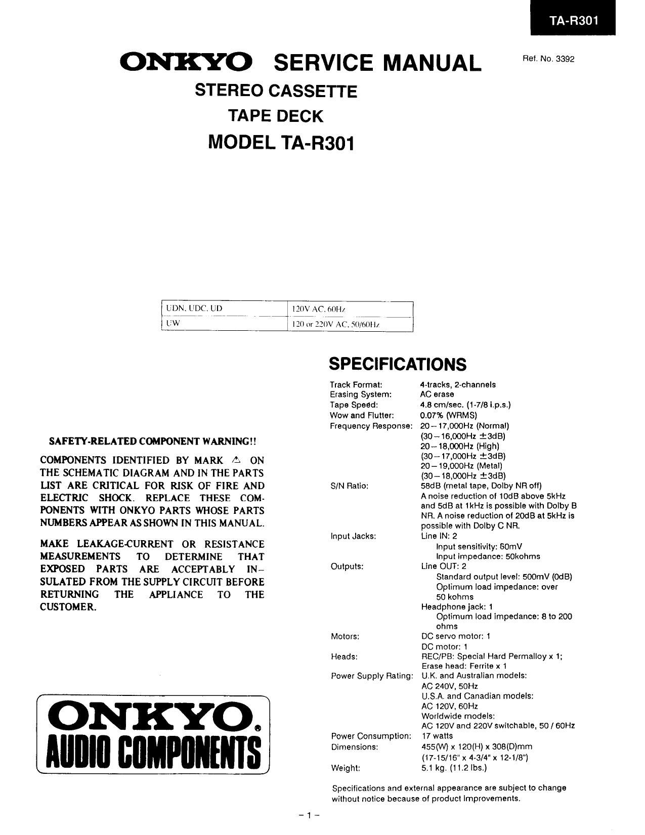
Onkyo TAR 301 Service Manual

This is the 13 pages manual for Onkyo TAR 301 Service Manual.
Read or download the pdf for free. If you want to contribute, please mail your pdfs to info@audioservicemanuals.com.

Page: 1 / 13
left right
Onkyo TAR 301 Service Manual

Extracted text from Onkyo TAR 301 Service Manual (Ocr-read)


Page 1

ONKYO SERVICE MANUAL

STEREO CASSETTE

TAPE DECK

MODEL TA-FI301

C UDC. UD

SAFETY-RELATED COMPONENT WARNING

COMPONENTS IDENTIFIED BY MARK A ON
THE SCHEMATIC DIAGRAM AND IN THE PARTS
LIST ARE CRITICAL FOR RISK OF FIRE AND
ELECTRIC SHOCK. REPLACE THESE COM-
PONENTS WITH ONKYO PARTS WHOSE PARTS
NUMBERS APPEARAS SHOWN IN THIS MANUAL.

MAKE LEAKAGE-CURRENT 0R RESISTANCE
MEASUREMENTS TO DETERMINE THAT
EXPOSED PARTS ARE ACCEPTABLY IN-
SULATED FROM THE SUPPLY CIRCUIT BEFORE
RETURNING THE APPLIANCE TO THE
CUSTOMER.

ON KYO.
IIIIIIII IIIIIIPIIIIIIIIS

IZUV AC fiilH/

i Ill) or 220V AC: Sll/fiilll/

TA-R301

Ref. No. 3392

SPECIFICATIONS

Track Format:
Eraslng System:
Taps Speed:
Wow and Flutter:

Frequency Response:

S/N Ratio:

Input Jacks:

Outputs:

Motors:

Heads:

Power Supply Rating:

Power Consumption:
Dimensions:

Weight:

racks, Z-channels
AC erase
4.8 cm/seo. (L718 itp.s.)
0.07% (WRMS)
20-17,000Hz (Normal)
(SO-16.000Hz :SdB)
20-1590on (High)
(so-17.0mm: tents)
20-19,000H1 (Metal)
(30-18.000Hz iadB)
SBdB (metal tape, Dolby NR o")
A noise reduction of 10dB above 5kHz
and 5dB at (Hz is possible with Dolby B
NR. A noise reduction at 20dB at 5kHz is
possible with Dolby C NR:
Llne IN: 2
Input sensitivity: GOmV
Input impedance: sokohms
Llne OUT: 2
Standard output level: SOOmV (OdB)
Optimum load impedance: over
50 kohms
Headphone jack: 1
Optimum load impedance: 8 to 200
ohms
DC servo motor: 1
DC motor: 1
REC/PB: Special Hard Permalloyx 1:
Erase head: Ferrite x 1
UK and Australian models:
AC 240V. 50Hz
U.S,A. and Canadian models:
AC 120V, 60Hz
Worldwide models:
AC 120V and 220V switchable. 50 / Gon
17 watts
455(W) x 120(H) x 308(D)mm
(17-15/16 x 443/4" x 12-1/8")
5.1 kg. (112 lbs.)

Specifications and external appearance are subject to change
without notice because of product Improvements.

Page 3

TA-R301

ADJUSTMENT PROCEDURES

PRECAUTIONS TEST EQUIPMENT/T 001.8 REQUIRED:
l. Before :djustlueut. clean the following parts with an Audio oscillator
Ilchai lrloiuslend swab. Digital frequency counter
' record/playhaekllezd erase head Oscilloscope
pinell roller ° capstan Attenullor

AC voltmeter
Non-magnetic screw drlvcr
Test tapes
, TCC153 1 IO KHz, -l5dB
"'"° mm ll : 3 kHz, -10dn
M'IT-l 50 : Dolby level calibration
400th, tone IOOnWb/ln

2. Do not use magnetized screwdriver for adjustments.

1 Demagnetlze record/playback head with I head de-

Connection Llne Output Adiustment .
Item of instrument Input T981 tape Mode indicator point Adm Hemaks
Frequency
1 Tape counter to MTP l l 1 PB Frequency Semi-fixed on 3005:10Hz
speed LINE output counter the meter
terminal
AC voltmeter Maximum
Head and , and same
2 azimuth oscilloscope to TCC»153 PB glimmer iizgvaummh phase at fig-l
LINE output channels L
terminal and R
AC voltmeter
3 :13? to terminals M'lF- 150 PB 35mm E: {231113 300mV
TP-3 and TP-4 '
Frequency
OSC counter to BIflETAL TAPE Frequency 85kHzi2kHz
4 Block P40] read MX-C90 REC counter L453
loose coupling
AC voltmeter R461
5 HX~ to terminals METAL TAPE REC AC L451(Ch'L) Maximum R462
PRO voltmeter L-452(ch.R) V
T1371 and T112 maxtmum
ikHz,
Bias _10dB AC R46l(Ch L) Same level Input VR
6 current 3'2 211221-12 XL 090 REC/PC voltmeter R462(Ch.R) at REC/PB maximum.
-20dB
AC Attenutor or
REC 350mV
1 t AF OSC t
7 Rm fig-2 IkHz XL-lI 090 V0 "3 er mp"
level REC/PB AC R403(Ch.L) Same level
voltmeter R404(Ch.R) at REC/PB
Blank tape
NORMAL
HIGH
METAL
PLAY torqu


FF. REW torque.

Back tentlon .. 2 ~ 7g/cm