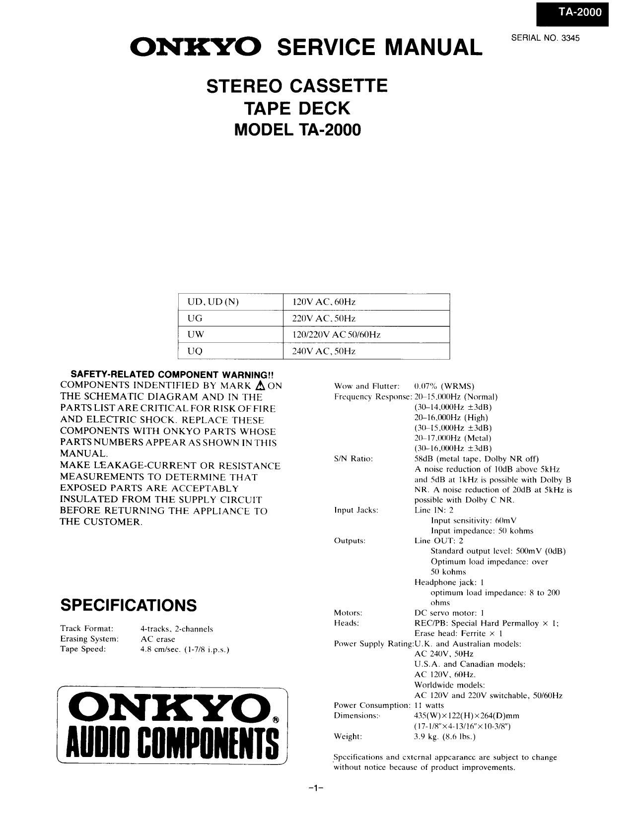
Onkyo TA 2000 Service Manual

This is the 15 pages manual for Onkyo TA 2000 Service Manual.
Read or download the pdf for free. If you want to contribute, please mail your pdfs to info@audioservicemanuals.com.

Page: 1 / 15
left right
Onkyo TA 2000 Service Manual

Extracted text from Onkyo TA 2000 Service Manual (Ocr-read)


Page 1

ONKYO SERVICE MANUAL

STEREO CASSETTE

TAPE DECK
MODEL TA-2000

UD UD (N) 120V AC, 60Hz

UG 220V ACSOHZ

UW 120/220V AC 50/60Hz

UQ 240V AC. SOHZ

SAFETYvRELATED COMPONENT WARNINGl!
COMPONENTS INDENTIFIED BY MARK A ON Wow and Flutter: 0.07% (WRMS)
THE SCHEMATIC DIAGRAM AND IN THE Frequency Respnnxe: ZIHSJMMHZ (Nurmzil)
PARTS LIST ARE CRITICAL FOR RISK OF FIRE (30441me7, ISdB)
AND ELECTRIC SHOCK. REPLACE THESE ZfHfimIHZ (H'gm
COMPONENTS WITH ONKYO PARTS WHOSE izlfiislllfillh if"?
PARTS NUMBERS APPEAR AS SHOWN IN THIS (Hg M65213
MANUAL _ . S/N Ratio: SXdB (metal tape. Dolby NR off)
MAKE LEAKAGECURRENT OR RESISTANCE A noise reduction of IUdB above SkHz
MEASUREMENTS TO DETERMINE THAT and SdB at IkH7. is possible with Dolby B
EXPOSED PARTS ARE ACCEPTABLY NR. A noise reduction of mar} at SkHz is
INSULATED FROM THE SUPPLY CIRCUIT possible with Dolby (? NRA
BEFORE RETURNING THE APPLIANCE TO PU JHCkSI UM IN: 2
THE CUSTOMER Input sensitivity: ()UmV
Input impedance: 50 kohms
Outputs: Line OUT: 2

Standard output level: SOOmV (OdB)
Optimum load impedance: over
50 k0th
Headphone jack: 1
optimum load impedance: 8 to 200

SPECIFICATIONS ohms

Motors: DC servo motor; 1

Heads: REC/PB: S ecial Hard Pcrmallo' X I;
Track Format: 4-tracks, 2-channels Erase head'pFerrite X 1 y
Erasing System: AC erase ' I

Pus 1er :U.K.'dA:l I' d1:
Tape Speed: 4.8 cm/scc. (1-7/8 i,prs.) 0" pp y 1 mg AC will» 53;? la" m0 6 5

USA. and Canadian models:
AC IZOV hOHZ.
Worldwide models:

( AC 120V and 220V switchable. 50/60Hz
' Power Consumption: 11 watts
® Dimensions:~ 435(W)X122(H)><264(D)mm

(l7« I [8" X 4-13/16"X III-313")

Aun'u BnMPUNENIs weight: 3.9 kg (8h lbs.)
J Specifications and external appearance are subject to change

'without notice because of product improvements

Page 2

T -2000

REC/PB levet _>

SERVICE PROCEDURES

1. Replacement of power supply cord

There are two power supply cord outlets on the strainrelief.
Insert them in prescribed direction to ensure safety. AS 3 (UD model) should be inserted lengthwnse and
other types of cords shOUId be inserted horizontally.

Power Supply Cord Power Supply Cord

Horizontal

length wtse
direction

direction

2. Insulating resistance measurement

Connect the insulating-resistance tester between the plug of
power supply cord and chassis.

Spethieation51500V more than IOMQ

HX PRO CIRCUIT OPERATION
EXPLANATION

I. Regarding recording frequency characteristic and bias
Ordinarily, if the recording bias current is increased. REC/PB
frequency rcsponse lcvcl in the high frequency region (about
[OKHZ and above) drops. and if thc bias is decreased. the
response riscs,

Drop
-\t

Frequency 9

BIBS decrease T

<__.___
Bias increase

REC/PB Ieve

2. Regarding the basic operation oIHX PR()(Refer to Fig. I)
The HX PRO uses the ,LL PCIZWCA IC. The operation is
in accordance with the followrng.

I) At (a). the recording bias rs added onto the audio signal.
and the recording signal is detected. This is the same as
the recording head recording the signal on the tape.

2) The signal of I) preserves the frequency response with
the integrated circuit of (b).

R435 + R43£ri7i (a 1)
2n X C435 x R435 X R433 ..
By means of the frequency of Fig, l. the frequency which
is effective from the beginning is determined. In the
ordinary situation, this is half the audio band (ltIKHz),
(IUKHz N 7.5KH2).

3) At (c). in order to use thc affected waveform after-ward.

absolute detection is carried out.

Frequency 2

Rise

l

Frequency ->

4) At (d), the waveform peak value is detected, The output
becomes the peak DC voltage.

5) At (e). the standard voltage and the voltage of (4) are
compared.

6) With the output of (e), the frequency generation level is
controlled (voltage controlled amplifier). That is, the bias
size is varied.

7) Summing up I) N 6):

At (a), the time constant (frequency) that is detected in
the recording signal is preserved. and above a certain
frequency and above a certain level, the VCA controls
the bias current by causeing its reduction. When this is
done. in the manor shown in the explanation of Item I
above. the frequency high region is raised. With this
control, the audio signal is instantaneously dealt with.

5

Regarding the operating conditions of the HX PRO

With equation (2. I) noted above, the effect begins at the
frequency thus determined.

Above a certain level the effect begins.

(Substantially 0 dB: In the vicinity of SOOmV line out)
The audio signal component level is dependent upon the
waveform after point (c).

1)