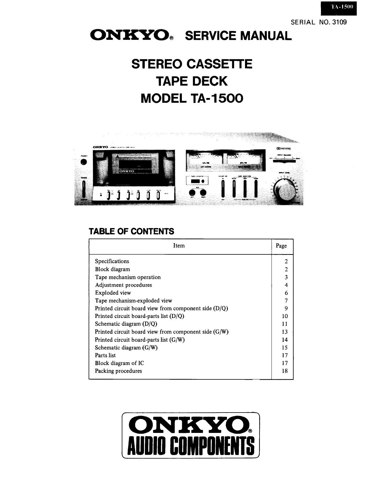
Onkyo TA 1500 Service Manual

This is the 13 pages manual for Onkyo TA 1500 Service Manual.
Read or download the pdf for free. If you want to contribute, please mail your pdfs to info@audioservicemanuals.com.

Page: 1 / 13
left right
Onkyo TA 1500 Service Manual

Extracted text from Onkyo TA 1500 Service Manual (Ocr-read)


Page 1

T VIEW)

SERIAL NO. 3109

ONKYO® SERVICE MANUAL

STEREO CASSE'ITE
TAPE DECK
MODEL TA-15OO

TABLE OF CONTENTS

Item Page
Specifications 2
Block diagram 2
Tape mechanism operation 3
Adjustment procedures 4
Exploded view 6
Tape mechanism-exploded view 7
Printed circuit board View from component side (D/Q) 9
Printed circuit board-parts list (D/Q) 10
Schematic diagram (D/Q) 11
Printed circuit board View from component side (G/W) 13
Printed circuit board-parts list (Cu/W) 14
Schematic diagram (G/W) 15
Parts list 17
Block diagram of IC 17
Packing procedures 18

ON KYO®
Alllllll IIIIMPIINENIS

Page 2

I \ bill)

SPECIFICATIONS

Track System:
Recording System:
Erasing System:
Tape Speed:

Wow and Flutter:

Frequency Response:

SignaHo-Noise Ratio:

Input Jacks:

4-track, 2-channel stereo
AC bias
AC erase
4.8 cm/sec.
0.06% (WRMS)
20 -15,000 Hz (30 -14.000 Hz i 3 dB)
(normal position tape)
20 - 16,000 Hz (30 - 15,000 Hz 1 3 dB)
(high position tape)
20- 16,000 Hz (30- 15,000 Hz a 3dB)
(metal position tape)
58 d8
(metal position tape, Dolby NR out)
A noise reduction of 10 dB
aboveS kHz and 5 dB at 1 kHz
is possible wish the Dolby NR in
Microphone Jacks: 2
Minimum input level: 0.3 mV/600n
Input impedance: 5 kn
Optimum mic impedance:
2000 - 50 kn
Line In: 2
Minimum input level: 50 mV
Input impedance: 50 kn
DIN Jack: 1 (GM)
Minimum input level: 0.1 mV/1 kn
Input impedance: 1 kn

BLOCK DIAGRAM

Outputs:

Motor:
Heads:

Semiconductors:
Power Supply
Power Consumption

Dimensions:

Weight:
Accessories:

Line Out: 2
Output level: 350 mV (at 0 VU)
Optimum load impedance: more than
50 kn

DIN Jack (G/W)
Standard output level: 350 mV (0 VU)
Optimum load impedance: more than
50 kn

Headphone Jack: 1
Optimum impedance: 8n - 200::

DC Servo motor: 1

Hard permalloy head and three gap ferrite

erase head

TR: 17 Diodes: 8 IC: 3 LED: 2

D: 120 V/ 60 Hz, G: 220 V/ 50 Hz,

W: 120/220 V 50150 Hz or

0: 240 V/50 Hz

13 W

418(W) x 122(H) x 270 (D) mm

164/2" x 4-11/16" x10-5l8"

4.4 kg (9.7 lbs)

Pin-type connecting cords: 2

' Specifications and external appearance are subject to change
without notice because of product improvements.

LINE
out© olherch vu METER
BALANCE Dolby sw METER
LINE v9 0N0 AMP @
IN ~e 9604
OFF -A
J other m 5605-2 Muhng
MIC om
INPUT 050,
V Muilng
M i
P e. E0, A 03"" NR -° _ 015: can] l-ove
MIC AMP em 0602
ouov,ouo3 , NE64BB 550" REC E0 AM P,
5601 v2
T. Pl 0 05
M
RIP HEAD /m #3
EC 550"" ' P LEVEL L P F REC LEVEL
LIOI
ssov-e an I I
seen-v0 [$1
P. e
E0_ J a 1 F UOS vB
REC
\J 50. $5017
BIAS vIv
ADJ
o: 225v E HEAD 7w. BIAS 1".
AC IN pow; _. 035 'rW-O
- Supply DC l3V >< LAM-0
> -" TAPE SEL