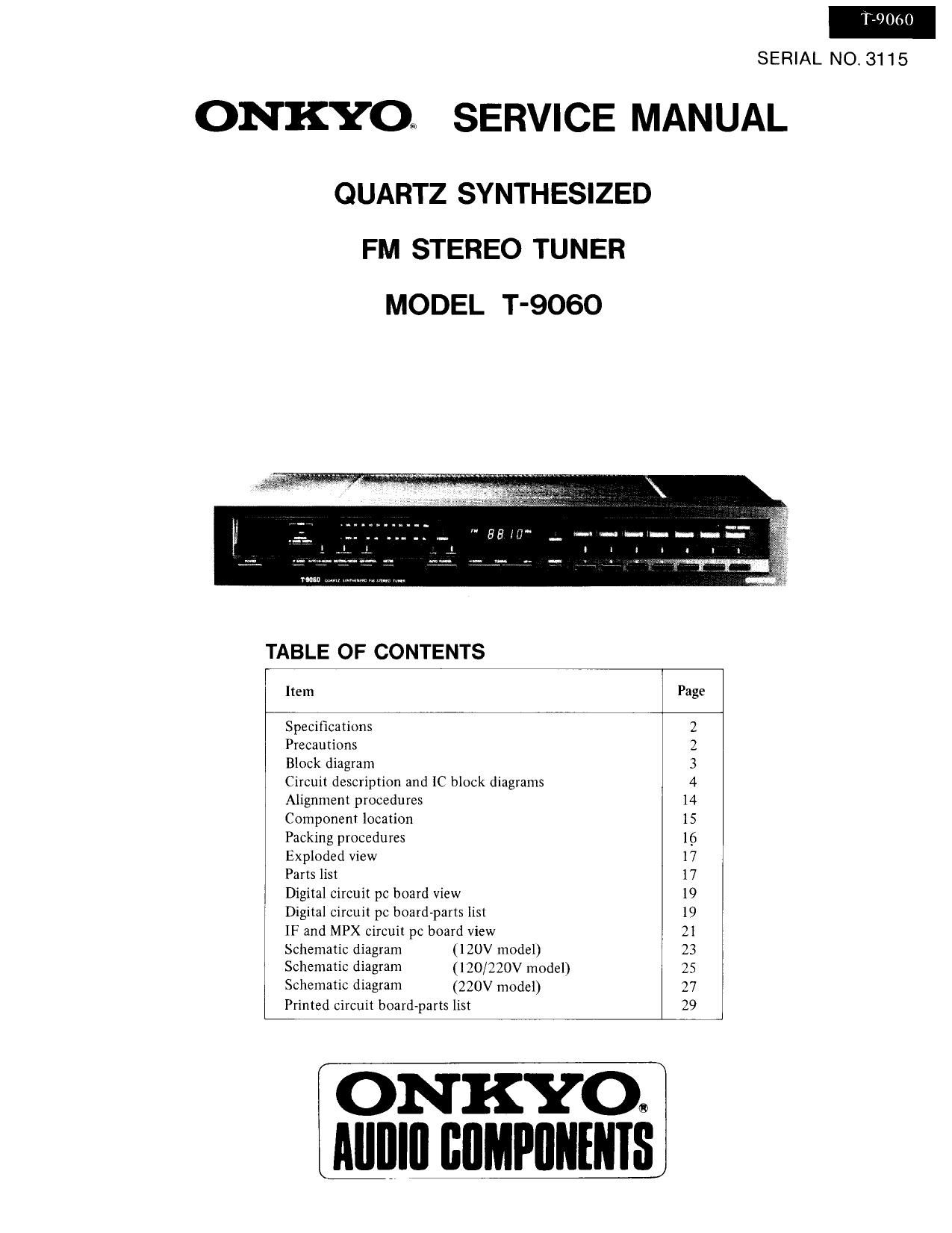
Onkyo T 9060 Service Manual

This is the 19 pages manual for Onkyo T 9060 Service Manual.
Read or download the pdf for free. If you want to contribute, please mail your pdfs to info@audioservicemanuals.com.

Page: 1 / 19
left right
Onkyo T 9060 Service Manual

Extracted text from Onkyo T 9060 Service Manual (Ocr-read)


Page 1

T3060

SERIAL NO. 3115

ONKYO SERVICE MANUAL

QUARTZ SYNTHESIZED
FM STEREO TUNER
MODEL T-9060

TABLE OF CONTENTS

Item Page
Specifications 2
Precautions 2
Block diagram 3
Circuit description and IC block diagrams 4
Alignment procedures 14
Component location 15
Packing procedures 16
Exploded view 17
Parts list 17
Digital circuit pc hoard View 19
Digital circuit pc board-parts list l9
IF and MPX circuit pc board view 2
Schematic diagram (120V model) 23
Schematic diagram (120/220V model) 25
Schematic diagram (220V model) 27
Printed circuit board-parts list 29

ONKYO®
Alllllll IIIIMPIINENIS

Page 2

T-1060

SPECIFICATIONS

D model

Tuning Range: 87.9 7 107.9 MHZ (200 kHz steps)

Usable Sensitivity: Mono: 10.3 dBf, 1.8uV
Stereo: 17.2 dBf, 4.0;.N
50 dB Quieting Sensitivity:
Mono: 14.7 dBf, 3.0/4V

Stereo: 36.1 dBf, 35uV

Capture Ratio: 1.0 dB
Image Rejection Ratio: 100 dB
IF Rejection Ratio: 100 dB
Signal-to-Noise Ratio: Mono: 81 dB (IHF)

Stereo: 73 dB our)

Alternate Channel Am: 80 dB IHF (:400 kHz IF: Normal)

AM Suppression Ratio : 55 dB
Total Harmonic
Distortion: Mono: 0.05% (1F: Wide)

Stereo: 0.13% (IF: Wide)

30 -15.000 Hz(+ 0.5 (13, -1.5 dB)
45 dB at 1 kHz (IF: Wide)

33 dB at 70 7 10.000 HZ (IF : Wide)
071.5V

Frequency Response:
Stereo Separation :

Output Voltage :

Muting Level: 172 dBf, 4.0pV

General

Power Supply: AC 120V, 60Hz

Antennas: 300 ohms balanced and 75
ohms unbalanced

Semiconductors: 8 FETs, 43 transistors,

181Cs. 61 diodes. 30 LEDs
Dimensions (W x H x D): 450 x 74 x 355 mm
(17-3/4 x 2-29/32" x 13-31/32)

Weight: 5.6 kg. 12.3 lbs.

Specifications and features are subject to change without notice.

PRECAUTIONS

1. Handling precautions of CMOS IC

1. All MOS devices should be stored or transported in
materials that are somewhat conductive. MOS deivces
must not be inserted into conventional plastic snow"
or plastic trays:

2. All MOS devices should be placed on a grounded
bench surface and operators should ground them-
selves prior to handling devices, since a worker can
be statically charged with respect to the bench
surface.

3. Nylon clothing should not be worn while handling
MOS circuits.

4. When lead straightening or hand solderng is necessary.
provide ground straps for the apparatus used.

5. Double check test equipment setup for proper
polarity of voltage before conducting parametric or
functional testing.

6. All unused device inputs should be connected to VDD
or VSS'

G/W model
Tuning Range: 875 7 108.0 MHZ (50 kHz steps)
Usable Senstivity: Mono: 10.3 dBf, 1 .BuV, IHF

1.4m! (S/N 26 dB.

40kHz Dev.) DIN
Stereo: 17.2 dBf, 4.0;1V. (IHF)

50W (S/N 46 dB.

40 kHz Dev.) DIN
50 dB Ouieting Sensitivity:
Mono: 14,7 dBf, 3.0pV
Stereo: 36.1 dBf,35pV

Capture Ratio: 1.0 dB
Image Rejection Ratio: 100 dB
IF Rejection Ratio: 100 dB
Signal-to~Noise Ratio: Mono: 81 dB (IHF)

Stereo: 73 dB (IHF)

70 dB DIN (1300 kliz. 40 kHz Dev.)
(IF : Normal)

AM Suppression Ratio: 55 dB

Total Harmonic Distortion:

Selectivity:

Mono: 0.05% (lF:Wide)
Stereo: 0.13% (1F2Wide)

30 715,000 Hz (+ 0.5 dB 71.5 dB)
45 dB at 1 kHz (1F: Wide)

33 dB at 70 7 10.000 Hz (IF: Wide)
0 - 1.5 V

17.2 dBf, 4.0;.1V

Frequency Response:
Stereo Separation:

Output Voltage:
Muting Level:

General

Power Supply: AC 120/220 Volts, 50/60Hz
AC 220 Volts, 50Hz

Antennas: 300 ohms balanced and

75 ohms unbalanced

XFETs, 43 transistors, 18

le, 62 diodes. 30 LEDs
Dimensions (W x H x D): 450 x 74 x 355 mm

(17-3/4 x 2-29/32 x 1331/32")
5.6 kg, 12.3 lbs.

Semiconductors:

Weight:

Specifications and features are subject to change without notice.

2. De-Emphasis Switch (bottom panel)
W models are equipped with a 50 usec 7 75 usec selector
switch. This is set to 50 psec at the factory, but may
have to be reset to 75 usec depending on the area where
the unit is used,
Europe:
U,S.A.:

50 usec
75 sec

3: FM Tuning Step Frequency Switch (back panel)
W models are equipped with a switch to change the FM
tuning step frequency from 50 kHz to 200 kHz. These
units are set to 50 kHz at the facotry; change to 200 kHz
if this gives better results in your locality.

to