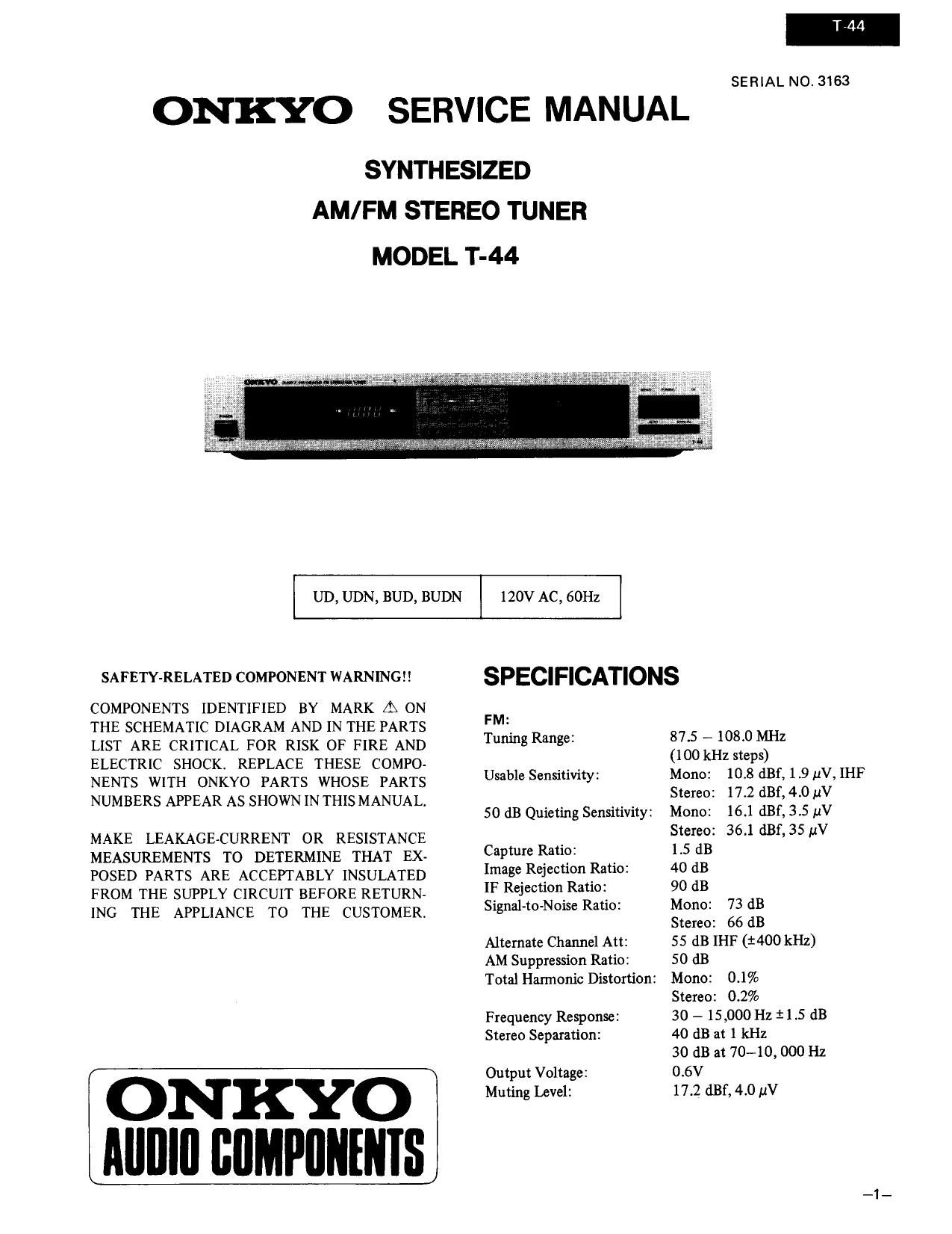
Onkyo T 44 Service Manual

This is the 18 pages manual for Onkyo T 44 Service Manual.
Read or download the pdf for free. If you want to contribute, please mail your pdfs to info@audioservicemanuals.com.

Page: 1 / 18
left right
Onkyo T 44 Service Manual

Extracted text from Onkyo T 44 Service Manual (Ocr-read)


Page 1

T744

SERIAL NO. 3163

ONKYO SERVICE MANUAL

SYNTHESIZED
AM/FM STEREO TUNER

MODEL T-44

UD, UDN, BUD, BUDN

120V AC, 60112

SAFETY-RELATED COMPONENT WARNING

COMPONENTS IDENTIFIED BY MARK [1: ON
THE SCHEMATIC DIAGRAM AND IN THE PARTS
LIST ARE CRITICAL FOR RISK OF FIRE AND
ELECTRIC SHOCKI REPLACE THESE COMPO-
NENTS WITH ONKYO PARTS WHOSE PARTS
NUMBERS APPEAR AS SHOWN IN THIS MANUAL.

MAKE LEAKAGE-CURRENT OR RESISTANCE
MEASUREMENTS TO DETERMINE THAT EX-
POSED PARTS ARE ACCEPTABLY INSULATED
FROM THE SUPPLY CIRCUIT BEFORE RETURN-
ING THE APPLIANCE TO THE CUSTOMER.

ONKYO
AIIIIIII BIIMPIIIIIIIIS

SPECIFICATIONS

FM:

Tuning Range: 87.5 - 108.0 MHz
(100 kHz steps)

Usable Sensitivity: Mono: 10.8 dBf, 1.9 V, IHF
Stereo: 17.2 (1131, 4.0 11V

50 dB Quieting Sensitivity: Mono: 16.1 dBf, 3.5 V
Stereo: 36.1 dBf,35 pV

Capture Ratio: 1.5 dB

Image Rejection Ratio: 40 (113

IF Rejection Ratio: 90 dB

Signal-to-Noise Ratio: Mono: 73 (13

Alternate Channel Att:
AM Suppression Ratio:

Total Harmonic Distortion:

Frequency Response:
Stereo Separation:

Output Voltage:
Muting Level:

Stereo: 66 dB

55 dB IHF (£400 kHz)
50 dB

Mono: 0.1%

Stereo: 0.2%

30 - 15,000 Hz $1.5 dB
40 dB at 1 kHz

30 dB at 70-10, 000 Hz
0.6V

17.2 dBf, 4.0 uV

Page 2

AM:

Tuning Range: 520-1710kHz
(10 kHz steps)

Usable Sensitivity: 25 av

Image Rejection Radio: 40 dB

IF Rejection Ratio: 30 dB

Signal-to-Noise Ratio: 40 dB

Total Harmonic Distortion: 0.8%

Output Voltage: 150 mV

General

Power Supply: AC120 V, 60 Hz

Semiconductors: FETs: 6 TR: 25 ICs: 10
Diodes: 37 LEDs: 20

Dimensions (WxHxD): 418 x73 x269mm
(16-1/2" x 2-7/8" x 10-5/8")

Weight: 3 .2 kg., 7.0 lbs.

Specifications and features ares subject to change without
notice.

SERVICE PROCEDURES
1. Replacing the lamp

This unit uses the lamp listed below.

circuit no. parts no. description
PL902 210054A PL6.3V 250mA, dial plate
illumination

2. Insulation resistance mesurement
Connect the insulating-resistance tester between the plug
of power supply cable and the nickel screw on the back
panel.
Specification; 500V, 3.3Mfl i 10%

TABLE OF CONTENTS

Specifications ............................ 1
Service procedures ......................... 2
Block diagram ............................ 3
Exploded view ............................ 4
Parts list ................................ 5
Circuit descriptions ......................... 6
Block diagram of IC ....................... 11
Printed circuit board view ................... 12
Adjustment procedures ..................... 13
Printed circuit board view ................... 15
Schematic diagram ........................ 17
Pc board-parts list ......................... 19
Packing view ............................ 20

3. Handling the CMOS [C T 44

This unit uses the CMOS le of 0203, Q702 and 0871.

1. All MOS devices should be store transported in mate
rials that are somewhat conductive. MOS devices
must not be inserted into conventional plastic
snow or plastic trays.

2. A11 MOS devices should be placed on a grounded
bench surface and operators should ground them»
selves prior to handling devices, since a worker can be
statically charged with respect to the bench surface.

31 Nylon clothing should not be worn while handling
MOS circuit.

4. When lead straightening or hand soldering is neces-
sary, provide ground straps for the apparatus used.

5. Double check test equipment setup for proper pola-
rity of voltage before conducting parametric or func-
tional testing

6. All unused device inputs should be connected to VDD
or Vss (Ground).

4. Memory Preservation

This unit does not require memory preservation bat-
teries. A built-in memory power back-up system preser-
ves contents of the memory during power failures and
even when the unit is unplugged. The unit must be plug-
ged in and the power switch turned on and off once in
order to charge the back-up system. Note that since this
is not a permanent memory, the power switch must be
turned on and off a few times each month to keep the
backup system operable. The period of time during
which memory contents are preserved after power has
last been turned off varies depending on climate and the
location and placement of the unit. On the average,
memory contents are protected over a period of 3 to 4
weeks (a minimum of 2 weeks) after the last time
power has been turned off. This period is shorter when
the unit is exposed to very high humidity or used in an
area with an extremely humid climate.

Page 8

3. Auto-search tuning circuit

0103 0807 + 5
FM IF E
SYSTEM 0807 32 A
5 N 8
._ __..T0 33 E 2
ST EREO o O
DECODER 0
0851
NOISE .
DETECTOR '9' 2
+8
0147 450kHz
Ml WW
1 0702
.1 vW-li I
F
All} 1; 2: Biz;
Limitrer
D
T , ,
Maximum frequency (fig. 3)

Station B

Station A

Start

Minimum frequency

(fig. 4)

4. FM/AM selector circuit

To tluorescen
indicator tube

The FM/AM selector circuit is shown in the diagram, fig. 5.
Pins 4 and 5 of 0702 are of the mutual reset type. For FM,
pin 4 is high and pin 5 is low; for AM, pin 4 is low and pin
5 is high. Because pin 5 is high and pin 4 is low during AM
reception, Q809 is on and Q808 is off, the analog switches
SW1 and SW2 of 0203 are on while SW3 and SW4 are off,
so an AM signal is output. Also, since 0706 goes to on and
0705 to off, the AM, kHz segments of the fluorescent
display are turned on. At the same time, Q145 is turned
off and 0144 turned on, so +B is supplied to the power
source terminal of the radio system pin 3 of 0142.

T-44

During FM reception, this is operated by the IF level detec-
tion and zero point detection circuits included in the FM [F
system [C of 0103 and by the noise component detection
circuit of 0851. When a station is tuned, the output of all
outputs go to the low level so Q807 goes from on to off,
causing pins 32 and 33 of the controller IC to go to the
high level to complete auto search tuning.

During AM reception, the AM IF signal is taken, ampli-
fied by Q147, limited to a certain amplitude by the D144
D145 limiter circuits and auto search tuning is completed
when the IF signal becomes 450 i 3 kHz.

0 Manual Tuning
When the UP or DOWN key is pressed, the frequency
goes up or down by one step. en either key is held
down, the frequency rapidly increases or decreases
(scans) and stops when the key is released. When either
end of the tuning range is reached, key input will no
longer be received and the frequency will stop at the
highest or lowest frequency.

I Auto Tuning
When the UP or DOWN key is pressed, scanning begins
in the up or down direction, stopping where there is a
radio station. Since auto scan is operated by a trian-
gular wave, scanning is begun in the opposite direction
the instant either end of the tuning range is roached.
Also, if the UP or DOWN key is pressed when the tuned
frequency is not at either end of the range, up or down
scanning will begin.

Pints at 0201
020' VCO terminal
of stereo decoder
0101 Pin 2 of 0103
-)}- FM [E Am .
stop Inpu

Mutin circuit

Pin of 0142
AM B+ Terminal
_-,

(fig. 5)

Pin 16 of 0201 goes to the high level, the VCO oscillator
stops, and pin 2 of 0103 goes to the high level so the FM
IF amp is also switched off. Also, during AM reception,
Q80] is turned on so the muting circuit is off. During FM
reception, all of the switching transistors mentioned above
perform the opposite operations to switch to the FM mode.
Figures in parenthese indicate transistor operation during
FM reception.