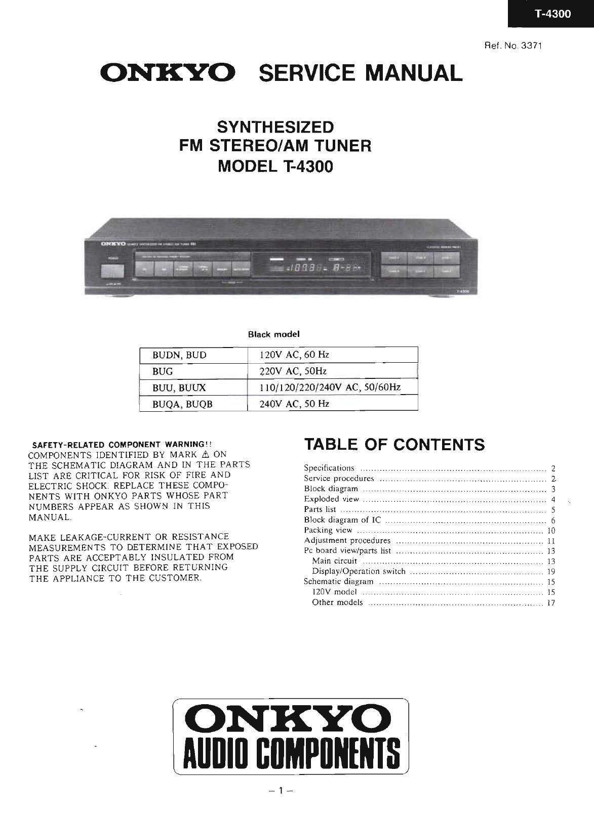
Onkyo T 4300 Service Manual

This is the 16 pages manual for Onkyo T 4300 Service Manual.
Read or download the pdf for free. If you want to contribute, please mail your pdfs to info@audioservicemanuals.com.

Page: 1 / 16
left right
Onkyo T 4300 Service Manual

Extracted text from Onkyo T 4300 Service Manual (Ocr-read)


Page 1

ONKYO

T-4300

Rel No,3371

SERVICE MANUAL

SYNTHESIZED
FM STEREO/AM TUNER

MODEL T-4300

Black model
BUDN, BUD 120v AC, 60 Hz
BUG 220v AC, 501-12
1 BUU. BUUX 110/120/220/24ov AC, 50/60Hz
I BUQA, BUQB 240v AC, 50 Hz

SAFETY-RELATED COMPONENT WARNING
COMPONENTS IDENTIFIED BY MARK A ON
THE SCHEMATIC DIAGRAM AND IN THE PARTS
LIST ARE CRITICAL FOR RISK OF FIRE AND
ELECTRIC SHOCK. REPLACE THESE COMPO-
NENTS WITH ONKYO PARTS WHOSE PART
NUMBERS APPEAR AS SHOWN IN THIS
MANUAL

MAKE LEAKAGECURRENT OR RESISTANCE
MEASUREMENTS TO DETERMINE THAT EXPOSED
PARTS ARE ACCEPTABLY INSULATED FROM
THE SUPPLY CIRCUIT BEFORE RETURNING

THE APPLIANCE TO THE CUSTOMER

TABLE OF CONTENTS

Specificalions . _.
Sen/ice procedures
Block diagram . .
Exploded mew . . .
Parts 115: .
Block diagram of 1C
Packing new . .
Adjustment procedures
Pc board view/parts list

Mam crrcuxt . ............

Display/Operation switch
Schematic diagram . . ..

120V model

Other models .............


ONKYO
Alllllfl BflMPllNINIS

_1-

Page 2

300

SPECIFICATIONS

Total Harmonic Distortion Mono: 0.1%

Tuning Range' 87 9-lm,9MHz(200kHz steps: U.S.A model) 516160: 0 2%
87.5-108.0MH2(50kHz steps: European model) Freqiiency Response: 30-15, OOUHz i1.5dB
87.971(Y7.9MH2(200kHz steps) or Stereo Separation: 40d}?! at 1km
87 5-108 0MH2(50kH1 steps) (Vtorldwide model) 30dB at 7U-IO,DOOI{Z
Usable Sensitivity Mono. ll ZdBt, L0 lV IHF Muting Level: 2.0 #V, 750hm
0 9 IV 7'50th DIN I7 ZdBI. 4.01-V
Stereo: 2.0 V 75ohms Output Voltage: SOOmV [120V model)
Mono: 11,2dBf, 2 O I'V IHIF (120V model) 750mV (Other models)
Stereo: 17.2dBf, 4.0 #V (120V model) AM:
SOdB Quieting Sensitivity: Mono: 1.7 #V 75,0th Tuning Range S3(}l710kH2(10kl-l7 steps) (U S.A. model)
Stereo: l.7 FV 750hm5 522-lollkHz( 9H; steps) (European model)
Mono. lérldBf, 3.5 #V (120V model) 530*1620kH7(lOkHz steps) or
Stereo: 36.1dBi, 35 #V (120V model) 531-I602kHZ( 9kHZ steps) (Worldwide moch)
Capture Ratio: 1.5dB Usable Sensrrivny. 25 l V
Image Rejection Ratio: 40dB (120V model) Image Rejection Ratio- 40dB
80:13 (Other models) ' ' IF Rejection Ratio AOdB
[F Rejection Ratio: 90dB Signal-torNoise Ratio: 40dB
Signalvto-Noise Ratio: Mono 73dB Harmonic Distortion: 0.8%
Stereo: 66dB Output voltage: 150mV
Alternate Channel . GENERAL:
Attenuation SOdB [HF [ 400ka (120V model) Dimensions(W><}-I> Selectivrty: SSdB DIN (IJOOkHz, 40kHz dev ) (Other models) [7143 X 2713/16" x l0-7/l6"
AM suppression Ratio SOdB Weight: 2 6kg . 5 7 lbs.

Specifications and tenturcs are subject to change without notice.

SERVICE PROCEDURES

1. Safety-cheek out
(Only U.S.A. model)
After correcting the original service problemperiorm
the following safety check before releasing the set to
the customer.

Connect the insulatingeresistance tester between the 4. Tuning Step Frequency Switch (Bapk Panel)

plug of power suuply cord and chassrs. W models are equipped with a switch for the AM (9kHZ/

Specifications 3,3Mohm :10? at 500.45 lOkHz) and FM (SOkHz/lOOkl-lz) bands. The switch

should be set to the proper steps for the radio broadcast

2, Memroy preservation frequencres in your area

This unit does not require memory preservation batteries.

A built-in memory power back-up system preserves contents 5. Changing the band step

0f the memory during DDWEY MINES and EVE when the With the exception of the models below, a BAND STEP

unit is unplugged, The unit must be plugged in and the

, . selector switch is not provided.
power swrtch turned on and off once in order to charge the

back-up system. Note that since this is not a pennanent FM

memory.the power switch must be turned on and off a few MODEL BAND erp ibiju

tIimes each month to keep the back-up system operative (U137 200kH-7 7% SOkl-izi Additional

he period of time during which memory contents are 1 . ,, ~ -

preserved after power has last been turned off varies WMZM Eliminated _i

depending on climate and placement of the unit,

On the average, memory contents are protected over a In D721/D723, 183133 (Part No. 223163) are used.

period of 3 to 4 weeks (a minimum of 2 weeks) after

the last time power has been turned off. This period is AM fl _

shorter when the unit is exposed to very high humidity or MODEL BANDleP 1

used in an area with an extremely humid climate W riltl'kHzggld-Iz- - Fliminfia
UG/UQ 9kHz +10kHz Additional

3. Voltage Selector (Back Panel)
W models are equtpped with a voltage selector to con-
form with local power supplies. Be sure to set this switch
to match the voltage of the power supply in your area


before turning the power switch on, This switch is set to 075:

220V at the factory. Voltage is changed by sliding the Q MICROPROCESSOR
groove in the switch with a screwdriver to the right or 0

left. Confirm that the switch has been moved all the way CD- c755

to the right or left before turning the power switch on :33 Super quucltor

Models without a voltage selector can only be used in
areas where the power supply is the same as that ofthe

DISPLAY CIRCUIT PC BOARD
unit.