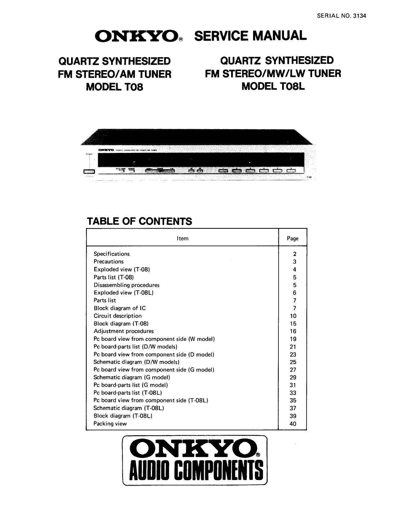
Onkyo T 08 Service Manual

This is the 27 pages manual for Onkyo T 08 Service Manual.
Read or download the pdf for free. If you want to contribute, please mail your pdfs to info@audioservicemanuals.com.

Page: 1 / 27
left right
Onkyo T 08 Service Manual

Extracted text from Onkyo T 08 Service Manual (Ocr-read)


Page 1

SERIAL N0. 3134

ONKYO® SERVICE MANUAL

QUARTZ SYNTHESIZED QUARTZ SYNTHESIZED
FM STEREO/AM TUNER FM STEREO/MW/LW TUNER
MODEL T08 MODEL T08L

TABLE OF CONTENTS

Item Page
Specifications 2
Precautions 3
Exploded view (Tv08) 4
Paris list (T-08) 5
Disassembling procedures 5
Exploded view (T~08L) 6
Parts list 7
Block diagram of IC 7
Circuit description 10
Block diagram (T-OB) 15
Adjustment procedures 16
Pc board view from component side (W model) 19
Pc board-parts list (D/W models) 21
Pc board view from component side (D model) 23
Schematic diagram (D/W models) 25
Pc board view from component side (G model) 27
Schematic diagram (G model) 29
Pc board-parts list (G model) 31
Pc board-parts list (T-08L) 33
Pc board view from component side (T-08L) 35
Schematic diagram (T-OSL) 37
Block diagram (T-08Ll 39
Packing view 40

ON KYOQ
Alllllll llllMl'llllllllS

Page 3

T-OBL

FM:
Tuning Range:

Usable Sensitivity:

50 d B Quieting Sensitivity:

Capture Ratio:

Image Rejection Ratio:
[F Rejection Ratio:
Signaho-Noise Ratio:

Selectivity;
AM Suppression Ratio:

Total Harmonic Distortion:

Frequency Response:
Stereo Separation:

Output Voltage:
Muting Level:

MW:

Tuning Range:

Usable Sensitivity:
Image Rejection Ratio:

PRECAUTIONS

87.5 - 108.0 MHZ (50 kHz steps)

Mono: l0.8 dBf, 1.9 V, IHI
1.6 uV (S/N 26 dB,
40 kHz Dev.) DIN
Stereo: 17.2 dBf, 4.0 LIV, IHF
50 MV (SIN 46 dB,
40 kHz Dev.) DIN

Mono: 16.1dBf, 3.5 uV
Stereo: 36.1 dBt, 35 uV
1.5 dB

45 dB

85 dB

Mono: 73 dB

Stereo: 65 dB

55 dB DlN t: 300 kHz, 40 kHz Dev.)
50:11?

Mono: 0.15%

Stereo: 03%

307 15,000 Hz 11.5 dB

40d}! at 1 kHz

30 dB at 100 710.000Hz

500 mV

13.2 dBt'. 2.5 av

522 - 1611 kllz (9 kH7 steps)
25 11V
45 dB

11 Rejection Ratio:
Signal-to-Noise Ratio:

Total Harmonic Distortion:

Output Voltage:

LW:

Tuning Range:

Usable Sensitivity:
Image Rejection Ratio:
1F Rejection Ratio:
Signal-(chaise Ratio:

Total Harmonic Distortion:

Output Voltage:

General
Power Supply:

Antennas:

Semiconductors:
Dimensions (W x H x 1)):

Weight:

30 dB
40 (IE
0.8%
150 mV

146 ~ 353 kHz [9 kHz steps)
35 14V

30 dB

30dB

40dB

0.8%

150 mV

European Models: AC 220 V, 50 Hz
Canadian Models: AC 120 V, 60 Hz
British & Australian Models:
AC 240 V. 50 Hz
Worldwise Models: AC 120 V. 60 Hz]
AC 220 V, 50 Hz
FM: 300 ohms balanced and
75 ohms unbalanced
AM (MW/LW): built-in loop antenna
and external terminal
4 Ili'l's. 36 transistors, 12 1C5
48 diodes, 15 LEDs
418 x 72 x 275 mm
(16-1/2 x 2-7/8" x 1043/16")
3.4 kg.7.51bs.

l. Replacing the C MOS IC

* Specifications and features are subject to change without notice.

3. Voltage Selector (rear panel)

1. All MOS devices should be stored or transported in
materials that are somewhat conductive. MOS devices
must not be inserted into conventional plastic snow"
or plastic trays.

2. All MOS devices should be placed on a grounded
bench surface and operators should ground them-
selves prior lo handling devices, since a worker can
be statically charged with respect to the bench
surface.

3. Nylon clothing should not be worn while handling
MOS circuits.

4. Whenlead straightening or hand soldering is necessary,
provide ground straps for the apparatus used.

5. Double check test equipment setup for proper
polarity of voltage before conducting parametric or
functional testing.

6. All unused device inputs shoud be connected to VDD
or V55.

Memory Preservation Batteries
Because stations stored in the memory by the FM/AM
preset keys would normally be lost when power is
turned off or the plug removed from the wall socket,
this unit requires two memory preservation batteries
to preserve the contents of the memory even when
power is turned off. Be sure to insert the correct type of
batteries into the battery holder in the bottom of the
Unit before turning on power for the first time.

_3.

l20/220V models are equipped with a voltage selector
to conform with local power supplies. Be sure to set
this switch to match the voltage of the power supply in
your area before turning the power switch on. Voltage is
changed by sliding the groove in the switch with a screw-
driver or similar instrument to the top or bottom posi-
tion. Confirm that the switch has been moved all the
way up or down before turning the power switch on. If
there is no voltage selector switch on the unit you have
purchased. it can only be used in areas where the power
supply voltage is the same as that of the unit.

. De-Emphasis Switch (rear panel)

120/220V models are equipped with a SOuscc 7 75usec
selector switch. This switch is set to SOusec at the
factory. but may have to be reset 75,usec depending on
the area where the unit is used:

Europe: SOusec

U.S.A. : 75psec

. AM Tinting Step Frequency Switch (bottom panel)

120/220V models are equipped with a switch to change
the AM Tuning step frequency from 9kHz. These units
are set to 9kHz at the factory; change to 10kHz if this
gives better results in your locality.