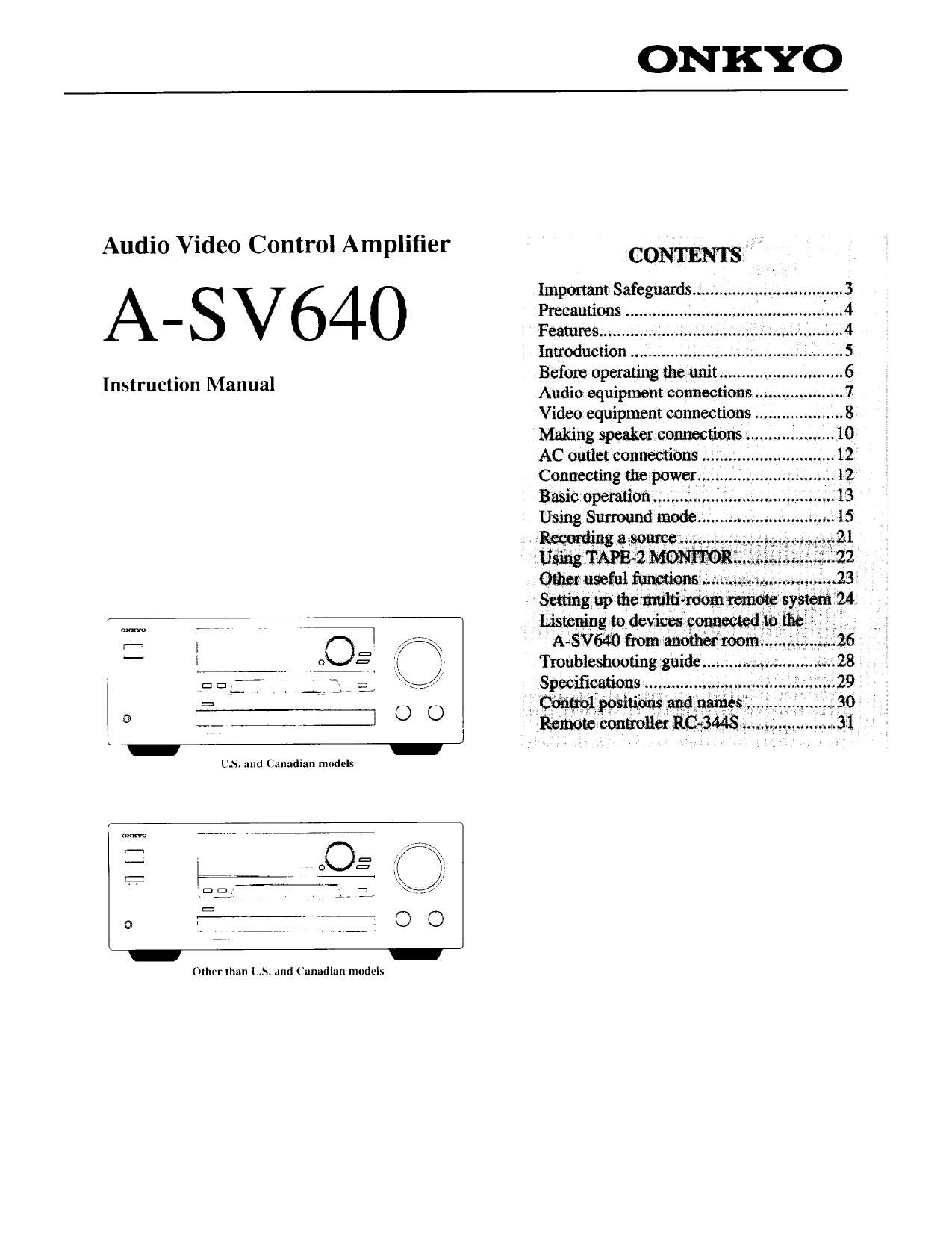
Onkyo SAV 640 Owners Manual

This is the 32 pages manual for Onkyo SAV 640 Owners Manual.
Read or download the pdf for free. If you want to contribute, please mail your pdfs to info@audioservicemanuals.com.

Page: 1 / 32
left right
Onkyo SAV 640 Owners Manual

Extracted text from Onkyo SAV 640 Owners Manual (Ocr-read)


Page 1

ONKYO

Audio Video Control Amplifier

A-SV64O

Instruction Manual

o = :( 1,
Fig" 17 2., a J
o f. fig: 0 O

Lima to devim confided in

Other Ihan LA and (Canadian models

CONTENTS "

Important Safeguards ............
Precautions .......... '
Features .........
Introduction" ..
Before operating the unit
Audio equipment connections
Video equipment connections
Making speaker. connections M
AC outlet connections

Bésic opemfionw
Using Surround mode.

A-Wémfimnmmom ... .
Troubleshooting guidcw. .
Specifications, 29

:Wposi \ V 3,0
Roman cumullm RC 3443 . I

Page 2

Thank you for purchasing an Onkyo Audio Video Control Amplifier, Please read this manual thoroughly before mak-

ing connections and turning on the power, Following the instructions in this manual will enable you to obtain optimum perfor-
mance and listening enjoyment trom your new Audio Video Control Amplifier. Please retain this manual tor future reference,

Supplied accessories

I Remote controller
2 Batteries (size AA, R6. or UM-3)

@@

RC-344S

The following accessories are available only for worldwide

models.
N

I CV plug (Shape may vary
according to the area where
purchased.)

FCC Information for User

CAUTION:
Changes or modifications not expressly approved by the manur
facturer for compliance could void the users authority to 0ch
ate the equipment.

NOT E:
This equipment has been tested and found to comply with the limits
for a Class B digital device. pursuant to Ptu't |5 of the FCC Rules
These limits are designed to provide reasonable protection against
harmful interference in a residential installation. This equipment
generates, uses. and can radiate radio frequency energy and. if not
installed and used in accordance With the instructions. may cause
harmful interference to radio communications. However, there is no
guarantee that interference will not occur in a particular installation,
If this equipment does cause hamittil interference to radio or tclevi-
sion reception. which can be determined by turning the equipment
off and on. the user is encouraged to try to correct Ihe Interference
by one or more of the followmg measures:
0 Reorient or relocate the receiving antenna
0 Increase the separation between other equipment and the

receiver,
0 Connect the equipment into an outlet oil a circuit different
from that to which the receiver is connected.

O Consult the dealer or an experienced radio/TV technician for help

Replacement and mounting of an AC plug on the power supply cord
of this unit should be performed only by qualified service personnel.
O IMPORTANT
The wires in the mains lead are colored in accordance with the fol,
lowing code:

Blue : Neutral

Brown : Live
AS the colors of the wires in the mains lead of this apparatus may
not correspond with the colored markings identifying the terminals
in your plug. proceed as follows:
The Wire which is coloured blue must be connected to the terminal
which is marked with the letter N or coloured black.
The Wire which is coloured brown must be connected to the termie
nal which is marked with the letter L or coloured red,
0 IMPORTANT
A 5 amp fuse is fitted in this plug. Should the fuse need to be
replaced. please ensure that the replacement fuse has a rating of 5
amps and that it is approved by ASTA or BSI to B81362. Check for
the ASTA mark or the 851 mark on the body of the fuse.
IF THE FITTED MOULDED PLUG IS UNSUITABLE FOR THE
SOCKET OUTLET IN YOUR HOME. THEN THE FUSE
SHOULD BE REMOVED AND THE PLUG CUT OFF AND DIS,
POSED OF SAFELY THERE IS A DANGER OF SEVERE
ELECTRICAL SHOCK IF THE CLIT OFF PLUG IS INSERTED
INTO ANY 1} AMP SOCKET.
If in any doubt. please consult a qualified electrician.

0 For models having a power cord With a polarized plug:
CAUTION : TO PREVENT ELECTRIC SHOCK. MATCH
WIDE BLADE OF PLLG TO WIDE SLOT. FULLY INSERT.

0 THIS DIGITAL APPARATUS DOES NOT EXCEED THE
CLASS B LIMITS FOR RADIO NOISE EMISSION FROM
DIGITAL APPARATUS SET OUT IN THE RADIO INTER-
FERENCE REGULATIONS OF THE CANADIAN DEPART-
MENT OF COMMUNICATIONS,

Sur Ies modeles dont la fiche est polari e:
ATTENTION: POUR EVITER LES Ci-iocs ELEC.
TRIQUES. INTRODUIRE LA LAME LA PLL'S LARGE DE LA
FICHE DANS LA BORNE CORRESPONDANTE DE LA PRISE
ET POUSSER JUSQUAU FOND.

0 LINTEREERENCE RADIO ELECTRIQUE GENEREE PAR
CET APPAREIL NUMERIQUE DE TYPE B NE DEPASSE
PAS LES LIMITES ENONCEES DANS LE REGLEMENT
SUR LES PERTURBATIONS RADIO ELECTRIQUES. SEC-
TION APPAREIL NUMERIQUE. DU MINISTERE DES
COMMUNICATIONS.

Declaration of Conformity

We. ONKYO EUROPE
ELECTRONICS GMBH
INDUSTRIESTRASSE 18/20
82] 10 GERMERING.
GERMANY

declare in own responsibility. that [he ONKYO product described
in this instruction manual is in compliance with the corresponding
technical standards such as EN55013. ENSSUZO. ENGOSSSAZI ,3
and EN60065

GERMERING. GERMANY E (W1

H. YAMAZOE
ONKYO EUROPE ELECTRONICS GMBH

Page 15

Using Surround mode

The A-SV640 features five Surround modes:
Make your choice of mode depending upon the type ot music you are listening to. the media used. and your personal preference.

Dolby Pro Logic: By using video tape and laser discs with the Dfl@l trade mark. you can decode four channel surround sound. \
Hall: This; mode simulates the atmosphere of a concert hall. Intended for classical music.
Live: This mode reproduces the feeling of a live performance.
Arena: This mode recreates the feeling of listening to a pop concert in a domed stadium.
l Studio: This mode reproduces the ambience of a recording studio.
Surround off tSTEREO): This mode is; used when you dont use the Surround mode. All input sound is output from the front
\pLuhLFS directly.

You can set the volume level of the channels for each Surround mode individually. Since the volume level for all channels is set to
your settings during the test tone operation. we recommend that you set the volume level for each Surround mode individually after
you set each channels volume level in Dolby Pro Logic mode.

NOTE:
0 The A-SVo-lO memoriLes the most recent surround settings. For example. it' you selected VIDEOel as an input selector and
chose "Hall" for Surround mode. selecting VIDEO-l next time will automatically select Hall" as a Surround mode.

\ 0 When you select MULTl SOYRCE In a Surround mode. the Surround mode will automatically turn off.
\

SURROUND
PARAMETER
477,7.

l :1 F7 : 9, :1)
;_~ ' a i\\ SURROUND
" MODE
(.7 [ 2 O . Q-
.,_ i'
ENTER
SMART SCAN CONTROLLER

SURROUND t- 5-», . s- as Ié-

]. Press the SURROUND button.
One of the SutTound mode indicators will light up.

2. Rotate the SMART SCAN CONTROLLER clockwise
or counterclockwise to select the desired Surround
mode.

Alternatively. press the SURROUND MODE button
repeatedly on the remote controller.

The names ofthe various Surround modes will light up on
the display sequentially.

Remote controller

MODE

worse

1 Press the P RAMETER button after you have

\ \ selected a Surround mode.
One of the Surround parameters will scroll on the display,
(e.g.. Center mode)

2. Rotate the SMART SCAN CONTROLLER to select
the parameter you wish to edit.

3. Press the ENTER button to confirm the selection.

\ The value of the selected parameter will flashes on the

display.

4. Rotate the SMART SCAN CONTROLLER to select
the desired value.

5. Press the ENTER button to confirm the entry.

3mm sow common

15

Page 21

Recording a source

REC OUT

\\

s
x, REC OUT

FIEC OUT

/

s
4 REC our \

/
\

REC OUT

s

/,
REC OUT \\

MPE 2
MON 02

REC OUT

You can use the A SVfi-II) to record either the source you tire
currently listening to or watching. or ii dit't'c nt souicc. (heck
that the components are connected to the A, No as shown
lli "Audio equipment connections and Video equipment
connections on pages 7 to 9,

[t the MultrRoom System equipment is connected. make
sure that the MR OFF indicator is lit while recording

1. Press an input selector button to select the desired
source.
2. Press the REC ()L'T button.
The REC OUT indicator will flash for eight seconds.
3. Press the REC ()UT button again while the REC ()LT
indicator is flashing.
The S tsourcet Wlii be shown in the right corner ot the
display.
Start recording on the recording component. then
start playing the selected source.

NOTE.

' [I you hate selected MULTI-CH INPUT in Step I. the
REC OUT will output VIDEOJ signal.

' Do not adjust an} Ltmlt'tli\ on the A-SV640 Litter starting
the recording operation.

0 Pressing an input selector button while recording will
change the source being recorded.

0 When the TAPE-Z VIONITOR indicator is lit. only the
TAPE-2 source can be recorded. Even if a different input
selector button is pressed. the TAPE-2 MONITOR indica-
tor will remain lit,

4

1. While listening to or watching a source. press the REC
()lfT button.

2. Press an input selector hutton (other than MULTl-CH
INPUT) for the source to be recorded. while the REC
OUT indicator is flashing. (For example CDl

. The abbreviation for the selected source name uppeu... (in
the source display.

VIDEOeI (VI). VIDEO-I (Vii. VIDEOJ (V3I. TAPEVI
(Tl ). TAPE-Z (T2). TUNER tTU). PHONO (PH). CD ICD)

0 At this time. pressing the MULTIeCH INPUT vtili change
the current source to MULTIeCH INPUT.

3. Start recording on the tape deck or VCR. and start the
source selected in step 2.

liming Mannheim 31%? We 5;

I. To record different video and audio sources to a desti-
nation VCR, first, select the video source using the
input selector buttons.

2. Press the REC/PAUSE button on the destination VCR.

3. Press the REC OUT button.

The REC OL'T indicators flashes for eight seconds.

4. While the REC ()UT indicator is flashing. select the
audio source using the input selector buttons [other
than MULTI-CH lNIlfTI.

The selected music source is indicated on the display, For
example. CD".

5. Start recording on the destination VCR. and then
start playback on the video and audio sources.

The Video and audio sources are recorded by the destinae
lion VCR.

21

Page 24

Setting up the multi-room remote system

[king the optional .V'lulleroom intent equipment it\ well tts u power Alllplll'lc'l and connectingy components tts shoon in thc tollowrng titu-
grttms wtll enuhle you to control them from the main room (where the system is locutedt us well us trotn another room tstthrrooml.

us. and Canadian models (Xantech Multiple-Room systems)
Do not plug In the power cord until all connections have been made.

Mttke connections as shown in the Connection Diagram below Make sure all components ute correctly connected,

I Connecting components equipped with ()nkyo RI connectors

MAIN ROOM \ SUB-ROOM

t Onkyo Components

7 7 7773 gpnrfiectrngr
A>SV540 °c
Speaker 1

Speaker
(Mann room)\

(Main room)

:2 Speaker
r (Subveom)

Supply \

lfl , ,1 ,
(Power Amplifier)

I Connecting components not equipped with ()nkyo F" connectors

5 Emitter MAIN ROOM l SUB-ROOM

iron 7 7
0M0 er 4 Remote
Sensor

wSpeaker\
i'lMam room) 2 Speaker

(Sub-
room)

C ,
S eaker
( am room)

2 Speaker
(Subrroom)

Power 4

Supply E

(Power Amplifier)

Connection Diagram Speaker A (Mam Room)

A-SV640

(3
MULTI
SOURCE

Connecting block

E: ji

Speaker B (Sub room)

I, Set up the Onkw RI components,

2 Connect the suhrroom speaker czihles lt
the FRONT REMOTE SPEAKERS
terminal on the Aesvmo.

You can use tt power amplifier to enjoy
powerful sound tn the subrl'oom. l-olr
low Steps 2-l and 2-2 to set it up.

2-] Connect the A-SV640 to the power

amplifier.

272. (onneet the sub-room \pcltktf cables
to the speaker terminal on the power
amplifier:

3 install the Connecting Block in the
mam room. then connect it to the A-
SVo-Ltl

4' install the Remote Sensor in the suhr
room then connect it to the Connecting
Block in the ntttin mom.

1, Connect the components to the A-
SVo-ifl,
Make the connections described above
in steps 2 through 4.

5. Install the Emitter so that its sensor is
directed toward the components. then
connect it to the APSV640.

To operate components positioned out 01

range of the emitter:

6, Connect these components to the A-
SV640

7. install another Emitter so Ihill its sen-
\UT is directed toward these compo-
nents. then connect it to the
Connecting Block.

Emitter

ecu:-

Power supply 4

HE]

PFlE OUT

FRONT
REMOTE
SPEAKERS

©©
©©

2

Power Amplifier

24

Remote sensor

SUB ROOM

...n.".n............................a