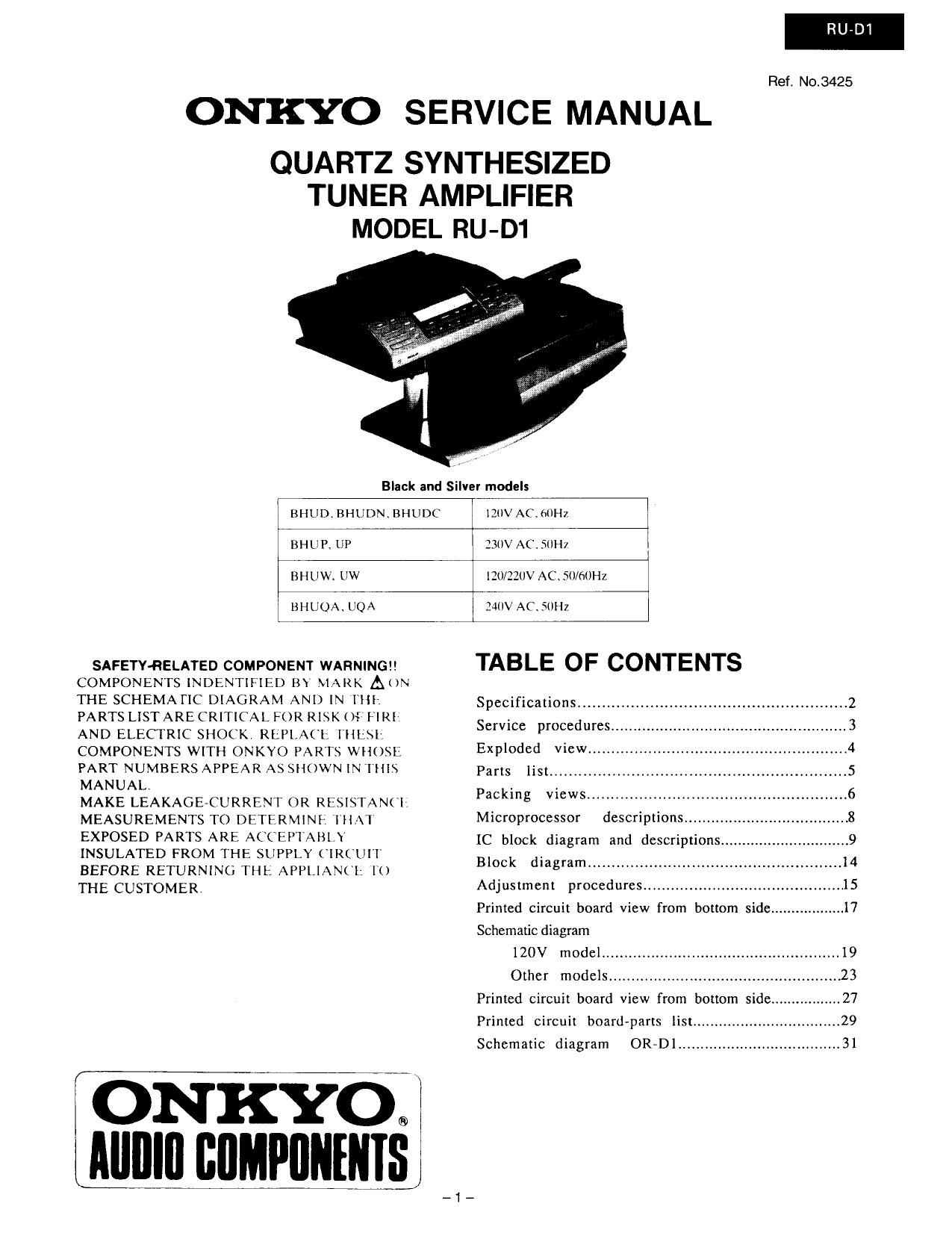
Onkyo RUD 1 Service Manual

This is the 24 pages manual for Onkyo RUD 1 Service Manual.
Read or download the pdf for free. If you want to contribute, please mail your pdfs to info@audioservicemanuals.com.

Page: 1 / 24
left right
Onkyo RUD 1 Service Manual

Extracted text from Onkyo RUD 1 Service Manual (Ocr-read)


Page 1

RU-DI

Ref. No.3425

ONKYO SERVICE MANUAL

QUARTZ SYNTHESIZED
TUNER AMPLIFIER
MODEL RU-D1

Black and Silver models

BIIUD. BHUDN. BHUDC

IZUV AC. MIMI.

BHLiP. UP

330V AC. SUII7

BIIUW. UW

IZO/ZZUV AC. 50/60Hz

BI IL'QA. UQA

Z40V AC. SUHZ

SAFETYRELATED COMPONENT WARNING?!
COMPONENTS INDENTIHED BY MARK ANN
THE SCHEMATIC DIAGRAM AND [N THE:
PARTS LIST ARE CRITICAL FOR RISK 0:" H RI
AND ELECTRIC SHOCK. REPLACI; THESI:
COMPONENTS WITH ONKYO PARTS WHOSE
PART NUMBERS APPEAR AS SHOWN IN [HIS
MANUAL
MAKE LEAKAGE-CURRENT OR RESISTANLI
MEASUREMENTS TO DETERMINE: 'I'IIAI
EXPOSED PARTS ARE ACCEPTABI \
INSULATED FROM THE SUPPLY CIRCUIT
BEFORE RETURNING THE APPLIANCI: [0
THE CUSTOMER.

(ONKYO. I

MIIIIII BIIMPIIIIIIIISJ

_1__

TABLE OF CONTENTS

Specifications ......
Service procedure
Exploded View...
list .............................................................. 5
Packing views .......................

Parts


Microprocessor descriptions...
IC block diagram and descriptions
Block diagram ...................................................... I4
Adjustment procedures ............................................ 15
Primed circuit board View from bottom side .................. I7
Schematic diagram
120V model ..................................................... 19
Other models .................................................... 23

Printed circuit board View from bottom side. ...27

Primed circuit board~parts list ................

Schematic diagram ORrDl ..................................... 31

Page 10

LC7823N (Analogue switch)

Li M

12 n2
LOOMI scout
u R! TONE TONE SWITCH LC7536
L4 in PATTERN l 2 3 4 5 6 7 LOUDNESS
3°"? new: DIRECT+ S.BASS OFF OFF OFF OFF OFF ON ON OFF
u as HEAVY+S.BASS OFF OFF OFF OFF OFF OFF ON ON
L6 as CLEAR+SVBASS OFF ON OFF ON OFF ON ON OFF
Leon: new! SOFI'+S.BASS ON OFF ON OFF OFF ON ON OFF
L1 R1 VOCAL+StBASS ON OFF OFF ON ON OFF ON OFF
LCODM "COW DlRECl' OFF OFF OFF OFF OFF ON OFF OFF
V3.9.- HEAVYKDIRECT) OFF OFF OFF OFF OFF OFF OFF ON
to-L CLEAR-KDIRECT) OFF ON OFF ON OFF ON OFF OFF
VIM-.- 5 °' SOFI+(D1RECI') ON OFF ON OFF OFF ON OFF OFF
3: g VOCAL+(DIRECT) ON OFF OFF ON ON OFF OFF OFF
c5
Pin No. Terminal Description Pin No. Terminal Description
1 TONE l 30 TONE 1
2 TONEZ 29 TONEZ
3 LCOMI 28 RCOMl
4 TONE 3 Tone control terminals. 27 TONE 3 Tone control terminals.
5 TONE 4 Control the inside analogue Swilch 26 TONE 4 Control the inside analogue switch
6 LCOMZ at the serial data. 25 RCOMZ at the serial data.
7 TONES 24 TONES
8 TONE6 23 TONE6
9 LCOM3 22 RCOM3
10 TONE7 21 TONE?
11 chM4 20 RCOM4
12 V55 Negative power supply 19 VDD
(-15V) 18 RES Reset terminal, When power is turned
13 CE Chip enable terminaLConnect to the on,the condition or the analog switch
terminal SE]. of microprocessori is not delermined.When this
14 DI Serial data input terrninaLConnect to the terminal is "L".all analog switches
terminal DATA of microprocessor, are off.
15 CL Serial clock input tenninal.Connectto Lh 17 S Selector terminal
terminal CLOCK of microprocessori 16 V55 Ground terminal

AN7470 (FM Stereo Decoder)

mmmmmme

~-jr-l-i

m, mu mot nmo in
u m lOCK varsmce m»
l . mm. mm. a..."
t l I

Elia u m r. 3. IN: 1. u w. 1.

Mann 5w - u um um. --w u m
vcg a, omen mvmsa email
in
um
r-j-L no" A»

sm- [0
ntwovuvon
RCN

1.___1 w... :1
lil l_7.l m

mmmmm

_10_

DIEAUD N! no