Onkyo Integra CDC 3 Service Manual

This is the 23 pages manual for Onkyo Integra CDC 3 Service Manual.
Read or download the pdf for free. If you want to contribute, please mail your pdfs to info@audioservicemanuals.com.

Page: 1 / 23
left right
Onkyo Integra CDC 3 Service Manual

Extracted text from Onkyo Integra CDC 3 Service Manual (Ocr-read)


Page 1

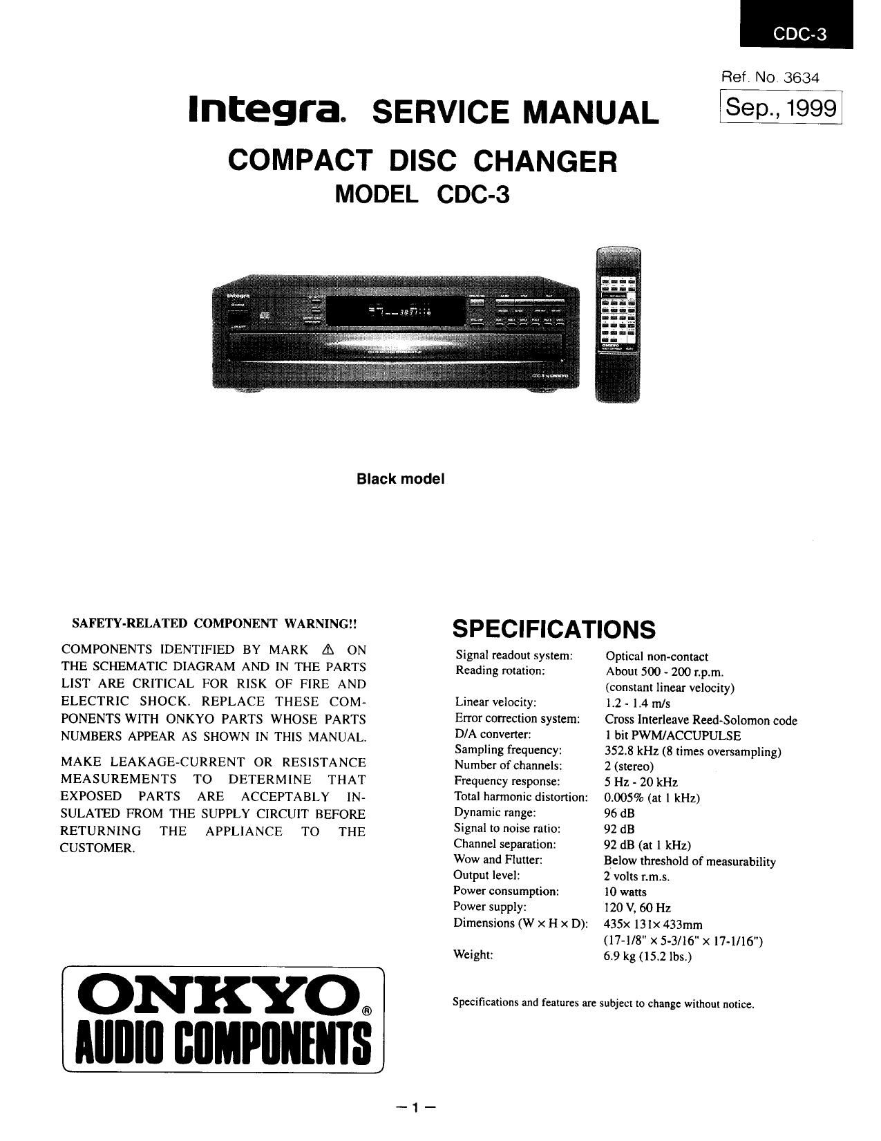
Integra. SERVICE MANUAL

COMPACT DISC CHANGER
MODEL CDC-3

CDC-3

Ref. NO 3634

Sep.

, 1999

Black model

SAFETY-RELATED COMPONENT WARNING

COMPONENTS IDENTIFIED BY MARK A ON
THE SCHEMATIC DIAGRAM AND IN THE PARTS
LIST ARE CRITICAL FOR RISK OF FIRE AND
ELECTRIC SHOCK. REPLACE THESE COM-
PONENTS WITH ONKYO PARTS WHOSE PARTS
NUMBERS APPEAR AS SHOWN IN THIS MANUAL.

MAKE LEAKAGE-CURRENT OR RESISTANCE
MEASUREMENTS TO DETERMINE THAT
EXPOSED PARTS ARE ACCEPTABLY IN-
SULATED FROM THE SUPPLY CIRCUIT BEFORE
RETURNING THE APPLIANCE TO THE
CUSTOMER.

ON KYO.
IIIIIIIII IIIIMPIIIIIIIIS

SPECIFICATIONS

Optical non-contact
About 500 - 200 rpm.
(constant linear velocity)
12 - 1.4 m/s

Signal readout system:
Reading rotation:

Linear velocity:

Error correction system:
D/A converter:
Sampling frequency:
Number of channels:
Frequency response: 5 Hz - 20 kHz
Total harmonic distortion: 0.005% (at | kHz)
Dynamic range: 96 dB

Signal to noise ratio: 92 dB

Channel separation: 92 dB (at l kHz)
Wow and Flutter:

1 bit PWM/ACCUPULSE

2 (stereo)

Output level: 2 volts r.mis,
Power consumption: l0 watts
Power supply: l20 V, 60 Hz

Dimensions (W x H x D): 435x 131x 433mm
(17-1/8" x 5-3/16 x l7~l/16")
Weight: 6.9 kg (15.2 lbs)

Specifications and features are subject to Change without notice

Cross Interleave Reed-Solomon code

3523 kHz (8 times oversampling)

Below threshold of measurability

Page 2

TABLE OF CONTENTS SERVICE PROCEDURES

Specifications 1 1. S afe ly ~check out
Caution on replacement of optical pick-up 2 After correcting the original service problem,perform
Protection of eyes from laser beam during servicing 3 the following safety check before releasing the set
Laser warning label 3 to the customer:
IC block diagrams and descriptions 4

8

9

Microprocessor connection diagram

Connect the insulatingnsistance tester between the
plug of power supply cord and chassis.

Microprocessor terminal description S pectfi cati o [5sz tltan lDMohm at 500
Care should be taken with the optical pickup 10
Trouble shooting 11
Initializing operation 13
Error message displayed in heat-running mode 14
Block diagram 15
Chassis exploded View 17
Parts list 19
Pick-up drive unit view 20
Printed circuit board-parts list 21
Printed circuit board view from bottom side 23
Schematic diagram 27
Adjustment procedures 29
Packing View 30

CAUTION ON REPLACEMENT OF OPTICAL PICK UP

The laser diode in the optical pickup block is so During repaincarefulley take the following precautions.
sensitive to static electricitysurge current and etc. (The following precautions are included in the service
that the components are liable to be broken down parts.)

or its reliability remarkably deteriorated.

PR EC A UTIONS

1.Ground for the work-desk. 3.Grounding for the human body.
Place a conductive sheet such 3 a sheet of copper Be sure to put on a wrist-strap for grounding whose
(with inpedance lower than IOMD) on the work- other end is grounded.
desk and place the set on the conductive sheet so Be particularly careful when the workers wear

that the chassis. synthetic fiber clothes. or air is dry.

2.6munding for the test equipment and tools. 4.Select a soldering iron that permits no leakage and
Test equipments and toolings should be grounded have the tip of the iron well-grounded.
in order that their ground level is the same the 5.130 not check the laser diode terminals with the
ground of the power source. probe of a circuit tester or oscilloscope.