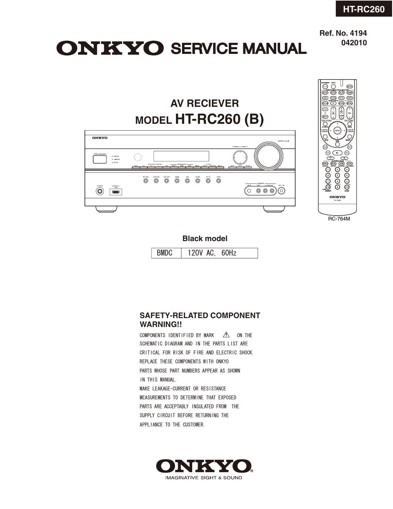
Onkyo HTRC 260 Service Manual

This is the 126 pages manual for Onkyo HTRC 260 Service Manual.
Read or download the pdf for free. If you want to contribute, please mail your pdfs to info@audioservicemanuals.com.

Page: 1 / 126
left right
Onkyo HTRC 260 Service Manual

Extracted text from Onkyo HTRC 260 Service Manual (Ocr-read)


Page 1

HT-RC260

Ref. No. 4194

ONKYO SERVICE MANUAL 2"

AV RECIEVER
MODEL HT-RC260 (B)

RC-764M

Black model

BMDC 120V AC, 60Hz

SAFETY-RELATED COMPONENT
WARNING

COMPONENTS IDENTIFIED BY MARK A ON THE
SCHEMATIC DIAGRAM AND IN THE PARTS LIST ARE
CRITICAL FOR RISK OF FIRE AND ELECTRIC SHOCK.
REPLACE THESE COMPONENTS WITH 0NKYO

PARTS WHOSE PART NUMBERS APPEAR As SHOWN

IN THIS MANUAL.

MAKE LEAKAGE-CURRENT OR RESISTANCE
MEASUREMENTS To DETERMINE THAT EXPOSED

PARTS ARE ACCEPTABLY INSULATED FROM THE
SUPPLY CIRCUIT BEFORE RETURNING THE
APPLIANCE TO THE CUSTOMER.

ONKYO®

IMAGINATIVE SIGHT SK SOUND

Page 2

SERVICE PROCEDURE

1. Replacing the fuses

This symbol located near the fuse indicates that the
fuse used is show operating type, For continued protection against
fire hazard, replace with same type fuse, For fuse rating,
the marking adjacent to the symbol.

EE' Ce symbole indique que le fusible utilise est e lent.

Pour une protection permanente, n'uti | iser que des fusibles de meme
type. Ce demier est indique la qu le present symbol est apposre.


I Canadian model

REF No. PART NAME DESCRIPTION
F6901 FUSE 12A-TUL-250V

F6902 FUSE 12A-TUL-250V
F901 FUSE 10A-UL/T-233
F901 or FUSE 10A-T/UL-ST2

2.To initialize the unit

PARTNO.

252301GR
252301GR
2523306R
25233SGR

HT-RC260

1. Press and hold down VCR/DVR button, then press ON/STANDBY button when the unit is powered on.
2. AfterC/ear is displayed, the preset memory and each mode stored in the memory are initialized and will

return to the factory settings, and turn to Standby mode.
3. Remove the AC cord from power line.

3. Safety check out
(U. S. A. model only)

After correcting the original service problem, perform the fol lowing safety check before releasing the unit to

the customer.

Leakage current Check

Measure the leakage current to a known earth ground (water pipe or conduct etc.) by connecting a leakage current
tester between the earth ground and exposed metal parts of the unit (input/output ground terminals, screw heads or

metal over lays eto. ).

Plug the power supply cord directly into a 120Vac 60Hz wall socket and turn ON/STANDBY button 0-

Any current measured must not exceed 0.5mA.

4. Memory Backup

This model uses a EE-PROM IC in order to retain radio presets and other settings. 80, memory contents will be

kept eternally with no care.

Page 16

608 HT-R680/ 980/ C260 DTR-20.2/ 3

VSP Update Procedure-6
2.3.4Writing begins when "Command Successful. Writiing FLASH. . is displayed

amamooa

:l flEp\vz>zao_a7zaas_osnovzoac.:xc-vl Excmicl Nib

- 27:95an flash .. g
- Blank checking ..

Dona.

Delay: Comma Succusstul.

unsung nun...

- Scan: address: DXDDOXSDOD

- Buffer 511:: 704980 1 DXOOOACICO ) Bytes

- Exam}. address space xequuea: 20 bus
Progress: 0.3

:1

Id

If the below message appears, the writing process has failed. Please try again.

v Hob

«I:

Timeout while waiting for response. Check connections and
reset: board. (Error CodeHJDDDOOEIZ)

Error executing hatch rile a: line 1.

chution tima: 1.155

3.3.SBatch completion (writing completion).
If the message named "Command Successful" appears as follows, the writing process is done.
Please OFF/ON the power supply.

dfll-EIWIMI


: 100.0