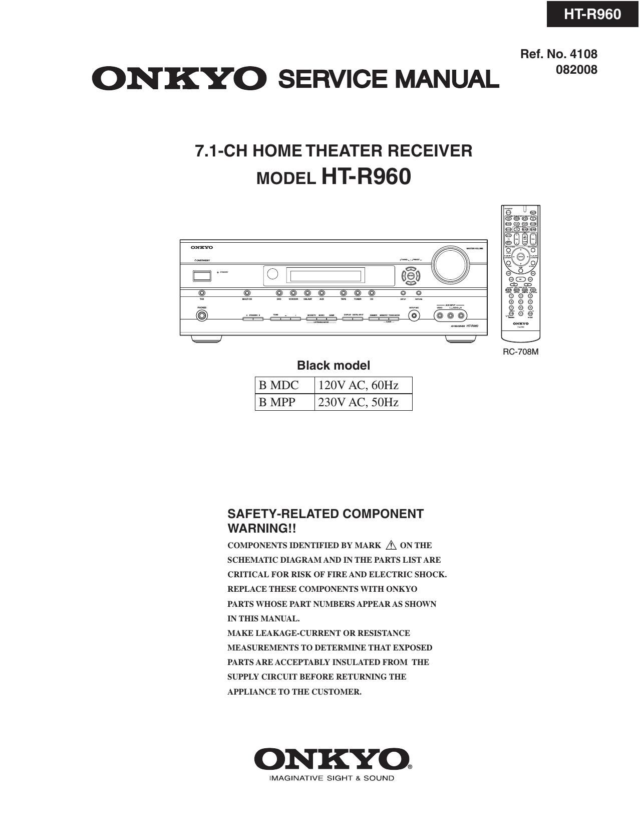
Onkyo HTR 960 Service Manual

This is the 191 pages manual for Onkyo HTR 960 Service Manual.
Read or download the pdf for free. If you want to contribute, please mail your pdfs to info@audioservicemanuals.com.

Page: 1 / 191
left right
Onkyo HTR 960 Service Manual

Extracted text from Onkyo HTR 960 Service Manual (Ocr-read)


Page 1

ONKYO SERVICE MANUAL

7.1-CH HOME THEATER RECEIVER

MODEL HT-R960

HT-R960

Ref. No. 4108

Black model

B MDC 120V AC, 60Hz
B MPP 230V AC, 50Hz

SAFETY-RELATED COMPONENT
WA R N I N G I I

COMPONENTS IDENTIFIED BY MARK A ON THE
SCHEMATIC DIAGRAM AND IN THE PARTS LIST ARE
CRITICAL FOR RISK OF FIRE AND ELECTRIC SHOCK.
REPLACE THESE COMPONENTS WITH ONKYO
PARTS WHOSE PART NUMBERS APPEAR AS SHOWN
IN THIS MANUAL.

MAKE LEAKAGE-CURRENT 0R RESISTANCE
MEASUREMENTS TO DETERMINE THAT EXPOSED
PARTS ARE ACCEPTABLY INSULATED FROM THE
SUPPLY CIRCUIT BEFORE RETURNING THE
APPLIANCE TO THE CUSTOMER.

ONKYO®

IMAGINATIVE SIGHT & SOUND

FIG-708M

082008

Page 44

IC BLOCK DIAGRAMS AND TERMINAL DESCRIPTIONS-13
Q3001 : AN15880A (Video SW for Receiver with Multi-signal)-2/3

TERMINAL DESCRIPTION (1/2)

Pin No. Pin name Type Descripion
1 Y1 Input Luminance signal input 1
2 Y2 Input Luminance signal input 2
3 Y3 Input Luminance signal input 3
4 Y4 Input Luminance signal input 4
5 Y5 Input Luminance signal input 5
6 VCCl Power supply 510 V power supply
7 BIAS Output Bias voltage
8 C1 Input Chrominance signal input 1
9 C2 Input Chrominance signal input 2
10 C3 Input Chrominance signal input 3
11 C4 Input Chrominance signal input 4
12 C5 Input Chrominance signal input 5
13 GND1 Groundl Ground
14 CY1 Input CY1 signal input
15 CY2 Input CY2 signal input
16 CY3 Input CY3 signal input
17 P131 Input PBl signal input
18 P132 Input PB2 signal input
19 P133 Input PB3 signal input
20 PR1 Input PR1 signal input
21 PR2 Input PR2 signal input
22 PR3 Input PR3 signal input
23 81 Input Logic control input 1
24 PROUT2 Output PROUT2 signal output
25 52 Input Logic control input 2
26 S3 Input Logic control input 3
27 PROUTl Output PROUTl signal output
28 S4 Input Logic control input 4
29 GNDS Ground Ground
30 SS Input Logic control input 5
31 VCCS Power supply 510 V power supply
32 PBOUT2 Output PBOUT2 signal output
33 PBOUTl --- PBOUTl signal output
34 NCl Output No connection
35 CYOUT2 Output CYOUT2 signal output

606

Page 64

IC BLOCK DIAGRAMS AND TERMINAL DESCRIPTIONS-33
08162 : Si|9185ACTU (Three Input, Single Output Deep Color HDMI Switch)-2/3

TERMINAL DESCRIPTION

System switching

Pin Name Pin # Dir Description

DSDAO, 30, Input / DDC IZC Data for respective port.

DSDAl, 50, Output

DSDA2 70

DSCLO, 31, Input DDC I1 C Clock for respective port.

DSCLI, 51,

DSCL2 71

RPWRO, 32, --- Port Tx detection input. Connect 5V input from HDMI connector.

RPWRl, 52,

RPWR2 72

Configuration

Pin Name Pin # Dir Description

HPDO, 16, Output Hot Plug Detect Output.

HPDl, 36,

HPDZ 56

HPDIN 76 Input Hot Plug Detect Input.

TPWR/ 12 Input / Optical IZC address. When RESET # is 0', pin will be used as an input to latch

I2CADDR Output 12C sub-address.

When RESET # is 1, this pin will be used as an output for TPWR indicating
selected Rx-port is alive.

EXTPSEL 55 Input External Port selection input pin. When this pin is 1 external pins, SCLiL and
SDAiL, will be use to select Rx-port as ExPSEL[1:O]. When 0, internal local 12C
register will be used to select Rx-port.

RSVDL 75 -»- Reserved for use by Silicon Image and must be tied low.

Control Pins

Pin Name Pin # Dir Description

RESET # 13 Input Reset Pin (Active LOW)

LSCL/ 74 Input Local Configuration / Status 11C Clock. When EXTSEL = 1, local CSL will be

EPSEL[1] used as External port selection pin, EPSEL[1].

LSDA/ 73 Bi-Di Local Configuration / Status 11C Data. When EXTPSEL = 1. local SDA will be

EPSEL[0] used as External port selection pin, EPSEL[O].

TSCL 78 Output Master DDC Clock (Open Drain Output) to HDMI receiver.

TSDA 77 Bi-Di Master DDC Data (Open Drain Output) to HDMI receiver.

CEC Pins

Pin Name Pin # Direction Description

CECiA 34 Input / Output HDMI compliant CEC I/O.

CECiD 33 Input / Output CEC interface to system microcontroller.

Page 81

FIRMWARE UPDATE-1
GENERAL

To check version of Main Microprocessor, DSP and Video FW
1. Press and hold down DISPLAY button, then press ON/STANDBY button when the unit is power on.
The main microprocessor version will be displayed on Front Display for about 3 seconds.

Ma in 1, 03/08630A *7 Version of Main Microprocessor FW
*Number depends on the version.

2. Press + (TONE) button while the version is displayed. Then, " DSPSH606:0861 1A " will be displayed
In this way, as + (TONE) button is pressed while a version is displayed, the next information will be displayed.
If - (TONE) button is pressed, the order will be reversed.

*Number depends on the version.

5 : v
E Main 1. 03/08630A *7 Version of Main Microprocessor FW (0701)
A : *Number depends on the version.
- (TONE) : + + (TQNE)
DSPSH606508611A 7 Version of DSP FW (0282)
E A . *Number depends on the version.
: a v
VD 1.20/08 6 06A 7 Version of VIDEO FW (08085)

3. Press ON/STANDBY button to power off.

UPDATE OF MAIN MICROPROCESSOR-1/2

Preparation for update
Hardware tool
1. PC(Personal computer) with RS232 terminal
OS : Windows XP or 2000
2. Flashwriterjig : OJFLASH and OJFLASHEX (including 2 Types : for non-Main)
Software tool
Writing soft : "Update_SR606Main1.2.zip" for Main microprocessor (File name depends on the version).
Unzip UpdateisR606Mainl.2.zip" in advance.

Connection and setup
1. While the target unit is off, connect OJFLASH and OJFLASHEX (for non-Main) to R5232 port of the PC.
2. Connect the FFC(Flat cable) of the jig to the connector slot on the rear panel.
3. Power on the unit.


; ~ OJFLASH~~~~~~1 ; 77777777 OJFLASHEX" ;
i i Conversion i
1 1 Flat cable .

M160 Flash starter 1 1 adaptor : Connector slot for update
R32320 terminal 1 1 I I
gig I 1 § :

E S[ 1 1 53[<- -,-> D
i i a -> Contact side

For non-main (4 line cut)

Rear panel

OOOOOOOO

PC(Personal computer) 8 Id ' 'd
--- O erlng SI 5"-

Target unit