Onkyo HTR 593 Service Manual

This is the 108 pages manual for Onkyo HTR 593 Service Manual.
Read or download the pdf for free. If you want to contribute, please mail your pdfs to info@audioservicemanuals.com.

Page: 1 / 108
left right
Onkyo HTR 593 Service Manual

Extracted text from Onkyo HTR 593 Service Manual (Ocr-read)


Page 1

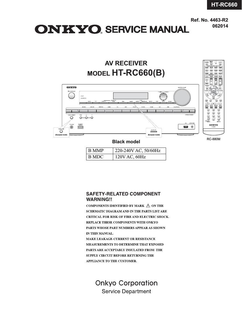
HT-RC660

Ref. No. 4463-R2

ONKYO® SERVICE MANUAL 2°

AV RECEIVER
MODEL HT-RC660(B)

{imp-an mom!)

RC»880M

Black model

B MMP 220-240V AC, 50/60Hz
B MDC 120V AC, 60Hz

SAFETY-RELATED COMPONENT
WA R N I N G ! !

COMPONENTS IDENTIFIED BY MARK A ON THE
SCHEMATIC DIAGRAM AND IN THE PARTS LIST ARE
CRITICAL FOR RISK OF FIRE AND ELECTRIC SHOCK.
REPLACE THESE COMPONENTS WITH ONKYO
PARTS WHOSE PART NUMBERS APPEAR AS SHOWN
IN THIS MANUAL.

MAKE LEAKAGE-CURRENT OR RESISTANCE
MEASUREMENTS TO DETERMINE THAT EXPOSED
PARTS ARE ACCEPTABLY INSULATED FROM THE
SUPPLY CIRCUIT BEFORE RETURNING THE
APPLIANCE TO THE CUSTOMER.

Onkyo Corporation
Service Department

Page 2

TX-NR535/636/737/838/DTR-30.6/40.6/50.6/HT-R593/693/993/HT-RC660

DEBUG MODE-1
AUDIO DEBUG MODE-1/5

The operations of DSP and DIR etc are able to checked by the information displayed on FL in this debug mode.
This information will help to analysing digital audio no sound trouble,

To set in Debug mode
1. Press twice the ON/ STANDBY key while pressing the DISPLAY key.

e-Q- 7 The version number of Microprocessor is displayed
M1'03/14307ALN only for 3 seconds

2 Press + (TONE) button while the version number of microprocessor is displayed.

e.g. N1.02/14210ALA _ ESE/\f/grrsgiosggglerZer of DSP Is displayed

3. Press DISPLAY button while the version number of DSP is displayed.

89 0A0002: :00 Step4
4. Proceed to the next step by pressing the DISPLAY key.
ANA .'o:NON:C: Step-2
4v
1:ANA 048k048k Step-3
4v
AUDIO dubug mode
2/0. 01 2. 053/4 Step-4 The status of DSP and DIR etc
4' will be displayed.
2:0:PCM :PCM Step-5
4v
00:X:F.'OFF Step-6
4v
SPO0F*00F00409 Step-7
4v
48 482568 TB Step-8 i
4v
L :0000 0000
vi
SW :0000 0000
4v
Exit

Page 21

TX-NR636/ 838/ HT-RC660/ HT-R993 DTR-3

OPERATION CHECK-10
COOLING FAN

Circuit
e.g.(TX-NR636) Value D/A output of the MPU
OFF 0V
LOW 1.7V
Thermal sensor MID 2.2V
06300 THERMAL 135 HIGH 2.5V
07°09 COOLING FAN
P (Main MIIIIIsoI'ocessor) Fan drive 0
ower amp' 3 FANCTRL 08701, Gog
08711
VOLH E 140 OD

Condition to operate

VOLH
Normal/ Bi-Amp Powerd Zone-2,3,4
OFF FF
Headplsgne LOW MID HIGH Heidplscgne LOW MID HIGH
OFF STOP STOP STOP STOP STOP STOP STOP STOP
THERMAL LOW LOW LOW LOW LOW LOW LOW LOW LOW
MID LOW MID M|D M|D MID M|D M|D MID
HIGH MID HIGH HIGH HIGH HIGH HIGH HIGH HIGH
THERMAL(Temparature of thermal sensor)
-30°C 52 60°C 63 65°C 67°C 95"C 100"C
H I H I H I Shutdown in
Shutdown I I I I I I . Shut down
. . OFF I I LOW I I MID I I HIGH 10 mmutes - -
| I I I I I I - Immedlatel
ImmedIatey I H I e I e continuously y
Hysteresis control
VOLH(Vo|tage of VOLH port)
0V 0.35V 0.4V 1.9V 2.0V 2.2V 2.3V 3.3V
l-> I l-> I l-> I
OFF 3 3 Low 3 i MID i 3 HIGH
1 4_L I 4_L I 4_L

Hysteresis control

How to check

1. How to check operation of Cooling Fan
See CONFIRMATION OF COOLING FAN OPERATION in OPERATION CHECK»4.

2. How to check the value of THERMAL and VOLH,
See CONFIRMATION OF OUTPUT VOLTAGE AND THERMAL SENSOR" in OPERATION CHECK-1.

Page 24

TX-NR636/ 737/ 838/ HT-RC660/ HT-R993/ DTR-30 40.

FIRMWARE UPDATE-2/2
USB Update (service mode)

[Procedure]
Overwriting is also possible.
1. Turn on the unit. It takes some time to start after you switch on the unit.
2. Select the USB input source.
3. Connect the USB storage device to USB port on the unit. Wait until Initializing ofUSB/NET finishes.

4. Hold down [DISPLAY] button and then press [ON/STANDBY] button twice.
Main version will be displayed, and HYBRID STANDBY indicator will start to flash.

5. Press [RETURN] button. NET -> ALLiD" will be displayed.

6. Select USB -> ALL7D by [PRESET(|efl/right)] cursors and [TUNING(up/down)] cursors,
then press [ENTER] button, updating will begin.

7. Wait until update is completed. When the update ends, Completed! is displayed.
(If you leave it, it automatically turns standby mode. )

8. Press [ON/STANDBY] button, and the unit turns on.
9. Check the new FW version number.


Ifthe procedure might not be succesful, please select USB -> ALLiM.