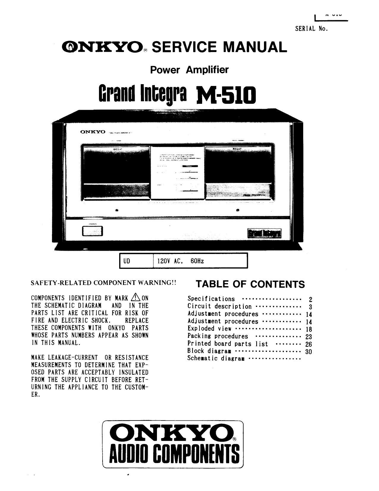
Onkyo Grand Integra M 510 Schematic

This is the 31 pages manual for Onkyo Grand Integra M 510 Schematic.
Read or download the pdf for free. If you want to contribute, please mail your pdfs to info@audioservicemanuals.com.

Page: 1 / 31
left right
Onkyo Grand Integra M 510 Schematic

Extracted text from Onkyo Grand Integra M 510 Schematic (Ocr-read)


Page 1

I a...

SERIAL No.

@NKYO SERVICE MANUAL

Power Amplifier

NM?! e M-sm

UD

120V AC,

80H:

SAFETY-RE1A\TED(XJMPCHQEN1U\RN1NCHI

COMPONENTS IDENTIFIED BY MARK ZERON
THE SCHEMATIC DIAGRAM AND IN THE
PARTS LIST ARE CRITICAL FOR RISK OF
FIRE AND ELECTRIC SHOCK. REPLACE
THESE COMPONENTS WITH ONKYO PARTS
WHOSE PARTS NUMBERS APPEAR AS SHOWN
IN THIS MANUAL.

MAKE LEAKAGE-CURRENT OR RESISTANCE
MEASUREMENTS TO DETERMINE THAT EXP~
OSED PARTS ARE ACCEPTABLY INSULATED
FROM THE SUPPLY CIRCUIT BEFORE RET-
URNING THE APPLIANCE TO THE CUSTOM-
ER.

TABLE OF CONTENTS

Specificathns ...... .. ......... . 2
Circuit description ------ - ------- 3
Adjustment procedures ...... ...... 14
Adjustlent procedures ----- ----- ~- 14
Exploded view ... ............ ..... 18
Packing procedures -------------- 23
Printed board parts list ------ -- 26
Block diagram .......... u ........ 30
Schelatjc diagram ............... .

ONKYO®

Alllllll COMPONENTS

Page 15

3.

Adjusting the idling current

i)

2)

Adjust-ent should be Iade with internal colponents at albient room
telperature. The following sequence is to be followed for adjust-enti
The voltage between plug P006 terlinals l and 2 on PC board NANA-2194a
should be approxilately ZUIV (DC) right after turning power on. and 20
IV ten Iinutes later. Adjustlents are Iade the seIi-fixed resistor R003
(R004) on PC board NANA-2194a. While doing this adjust-ant, short P006
terminals 3 and 4. While the unit is warning up LED D001 will light up

(ZOIIV i 10IV) .

Adjusting the Ieter circuit

1)

Adjusting the 0 setting on the Ieter
While power is OFF adjust the Zero Calibration Knob so that the later

needle reads 0 ".

NOTE 1: Do not execute this adjust-ent right after turning the unit off.

Wait until all electricity has been discharged before adjusting.

NOTE 2: After adjusting the 0 setting, turn the Zero Calibration Knob

2)

3)

4)

back slightly to allow sale play in the knob.
offset adjustment of the later circuit
After power has been UN for 5 minutes and with no signal inputs, use the
meter offset sell-fixed resistor R46 on PC board NAME-2198 to adjust the
Ieter needle to U .
Level adjust-ent of the leter circuit
Apply a 1 KHZ input to the input terlinals at a level that
yields an output of 15.49V (23.8 dBV), then use the Meter Level Adjust-
nent semi-fixed resistor R24 on PC board NAME-2198 to adjust the Ieter
needle to 0 dB.
Meter dalping adjustment
Using the METER OFF switch, make the needle wave fron 0 to 0 dB.

Then overshoot the needle once and stop it there.