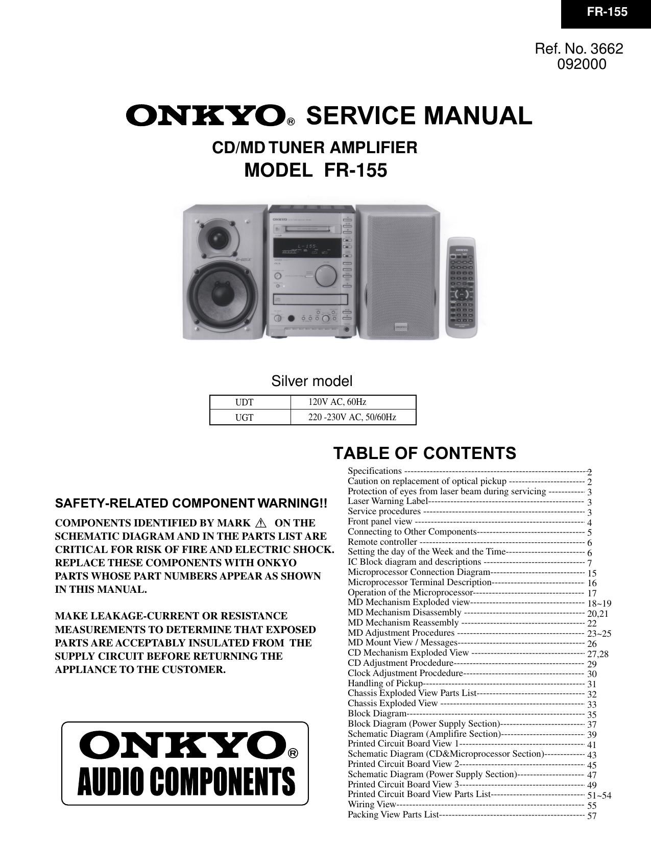
Onkyo FR 155 Service Manual

This is the 48 pages manual for Onkyo FR 155 Service Manual.
Read or download the pdf for free. If you want to contribute, please mail your pdfs to info@audioservicemanuals.com.

Page: 1 / 48
left right
Onkyo FR 155 Service Manual

Extracted text from Onkyo FR 155 Service Manual (Ocr-read)


Page 1

FR-155 SPECIFICATIONS 2 General Power supplyAC 220-230 V, 50/60 Hz AC 120 V, 60 Hz Power consumption63 W (220-230 V, 50/60 Hz) 82 W (120 V, 60 Hz) (Standby)7 W (Energy Save)1.5 W Clock precision monthly error: 30 seconds (at 25 degrees Celsius) Dimensions (W × H × D)205 × 154 × 356 mm 8-1/16" × 6-1/16"× 14" Weight5.5 kg, 12.1 lbs Amplifier Power output 2 × 26 W at 4 W EIAJ 2 × 21 W at 6 W EIAJ Rated Power 2 × 19 W min, RMS at 4 W 1 kHz no more than 0.2 % THD Dynamic power2 × 23 W at 4 W Total harmonic distortion0.4 % at rated power IM distortion0.2 % at rated power Damping factor25 at 8 -„¦ Sensitivity and impedanceLINE, TAPE: 150 mV, 50 kW CDR: 150 mV, 50 kW Frequency response10 to 50,000 Hz : +0dB / -3 dB Tone ControlS.BASS1: +4 dB at 40 Hz S.BASS2: +8 dB at 50 Hz S.BASS3: +4 dB at 10 kHz/ +8 dB at 50 Hz Signal to noise ratio LINE, CDR, TAPE: 100dB (IHF-A) Muting 50 dB CD player Signal readout systemOptical non-contact Frequency response10 Hz to 20 kHz ( 3 dB) Wow and flutterBelow threshold of measurability MD recorder Signal readout systemOptical non-contact Recording time320 minutes maximum (at LP4 mode) Frequency response10 Hz to 20 kHz ( 3 dB) Wow and flutterBelow threshold of measurability Tuner Tuning rangeFM: 87.50 to 108.00 MHz (50 kHz steps) AM: 522 to 1611 kHz (9 kHz steps) Usable sensitivityFM Mono: 11.2 dBf, 1.0 µV (75 W IHF) Stereo:17.2 dBf, 2.0 µV (75 W IHF) AM: 30 µV 50 dB quieting sensitivity FM Mono:17.2 dBf, 2.0µV (75 W ) Stereo:37.2 dBf, 20.0 µV (75 W ) Capture ratio2.0 dB Image rejection ratioFM: 85 dB AM: 40 dB IF rejection ratioFM: 90 dB AM: 40 dB Signal to noise ratioFM Mono : 73 dB IHF Stereo : 67 dB IHF AM: 40 dB SelectivityFM: 50 dB ( 300 kHz at 40 kHz devi.) Harmonic distortionFM: Mono: 0.7 % Stereo: 0.3 % AM: 0.7 % Frequency responseFM: 30 to 15,000 Hz ( 1.5 dB) Stereo separationFM: 40 dB at 1,000 Hz FM: 30 dB at 100 to 10,000 Hz Specifications and features are subject to change without noitce. CAUTION ON REPLACEMENT OF OPTICAL PICKUP The laser diode in the optical pickup block is so sensitive to static electricity, surge current and etc., that the components are liable to be broken down or its reliability remarkably deteriorated.During repair,carefully take the following precautions. (The following precautions are included in the service parts.) PRECAUTIONS 1.Ground for the work-desk. Place a conductive sheet such as a sheet of copper (with impedance lower than 10 Mohm) on the work- desk and place the set on the conductive sheet so that the chassis can be grounded. 2.Grounding for the test equipments and tools. Test equipments and toolings should be grounded in order that their ground level is the same the ground of the power source.3. Grounding for the human body. Be sure to put on a wrist-strap for grounding whose other end is grounded. Be particularly careful when the workers wear synthetic fiber clothes, or air is dry. 4. Select a soldering iron that permits no leakage and have the tip of the iron well-grounded. 5. Do not check the laser diode terminals with the probe of a circuit tester or oscilloscope. .

Page 2

FR-155 3 PROTECTION OF EYES FROM LASER BEAM DURING SERVICING This set employs a laser. Therefore, be sure to follow carefully the instructions below when servicing. WARNING!! SERVICE WARNING : DO NOT APPROACH THE LASER EXIT WITH THE EYE TOO CLOSELY. IN CASE IT IS NECESSARY TO CONFIRM LASER BEAM EMISSION, BE SURE TO OBSERVE FROM A DISTANCE OF MORE THAN 30cm FROM THE SURFACE OF THE OBJECTIVE LENS ON THE OPTICAL PICK-UP BLOCK. Laser Diode Properties Material: GaAS/GaALAs Wavelength: 780nm Emission Duration: continuous Laser output: max. 0.5mW* *This output is the value measured at a distance about 1.8mm from the objective lens surface on the Optical Pick-up Block. LASER WARNING LABEL The label shown below are affixed. 1. Warning label 2. Class 1 label "CLASS 1 LASER PRODUCT" LUOKAN 1 LASERLAITE KLASS 1 LASER APPARAT SERVICE PROCEDURE 1. Replacing the fuses3. Safety-check out (Only U.S.A. model) After correcting the original service problem perform the follwing safety check before releasing the set to the customer Connect the insulating-resistance tester between the plug of power supply cord and terminal GND on the back panel. Specifications: More than 10Mohm at 500V REF.NO. PART NO. DESCRIPTION F901 252157 1.25A-UL/T-237, Fuse
252083 0.4A-SE-EAW, Fuse NOTE :
: 120 V model only : 220 V~230 V model only This symbol located near the fuse indicates that the fuse used is show operating type, For continued protection against fire hazard, replace with same type fuse , For fuse rating, refer to the marking adjest to the symbol. Ce symbole indique que le fusible utilise est e lent. Pour une protection permanente, n'utiliser que des fusibles de meme type. Ce demier est indique la qu le present symbol est apposre. 1. Press and the hold down the CD STOP button , then press the STANDBY/ON button. 2. After " All lighting " is displayed, the preset memory and each mode stored in the memory, are initialized and will return to the factory settings. 3. Press the STANDBY/ON button. 4. Unplug the AC plug from the wall outlet. 2. To initialize the unit 4. Memory Preservation This unit does not require memory preservation batteries. A built-in memory power back-up system preserves the contents of the memory during power failures and even when the unit is un-plugged. The unit must be plugged in order to charge the back-up system. The memory preservation period after the unit has been unplugged varies depending on climate and placement of the unit. On the average, memory contents are protected over a period of a few weeks after the last time the unit has been unplugged. This period is shorter when the unit is exposed to a highly humid climate. 5. Changing the AM band step With the exception of the worldwide models, a tuning step selector switch is not provided. When you change the band step, change the parts as shown below. To 10kHz To 9kHz R748 open 1 kohms R749 1 koms open R748 and R749 on the microprocessor PC board (NADG-6933)

Page 15

FR-155 16 1 2 3 4 5 6 7 8 9 10 11 12 13 14 15 16 17 18 19 20 21 22 23 24 25 26 27 28 29 30 31 32 33 34 35 36 37 38 39 40 MICROPROCESSOR TERMINAL DESCRIPTION Q701:MPD780058GC-8BT PIN No. ROTEN2 ROTEN1 FLRESET GND SHUTDOWN RCREQ AVDD MDDATA RCDATA SCLK FLCE FLDATA FLCLK TXD RXD SQSO SENS SQCK CDCLK CDDATA CDXLT CDRESET CDPOWER OPEN CLOSE ACPOWER OPENSW CLOSESW SENS2 ECOLED RECVOL1 RECVOL2 GND RCPOWER MDRESET BAND0 BAND1 AM10K RDSEN Function I I O I O O I I O O O O O O I I I O O O O O O O O O I I I O O O I O O I I I I I I/O Pulse input pin 1 from rotary encoder. Pulse input pin 2 from rotary encoder. Reset signal output pin for FL driver IC(M66004) Ground pin. Output pin of power failure signal for MD mechanism microcomputer. Serial data output pin for communication of MD microcomputer. Power supply pin for A/D converter. Serial transfer data input pin from MD mechanism microcomputer. Serial transfer data output pin to MD mechanism microcomputer. Serial transfer clock output pin to MD mechanism microcomputer. Chip enable signal output pin for FL drover IC(M66004). Serial data output pin for FL drover IC(M66004). Clock data output pin for FL drover IC(M66004). Output pin for flash writer. Input pin for flash writer. Input pin of subcode data from CD signal processor IC(CXD2589). Input pin of sens data from CD signal processor IC(CXD2589). Clock signal output pin for read out to signal processor IC(CXD2589). Command output pin for transfer the clock signal to CD signal processor IC(CDX2589). Command output pin for transfer the data signal to CD signal processor IC(CXD2589). Command output pin for transfer the latch signal to CD signal processor IC(CXD2589). Reset signal output pin for CD circuit ICs(CXD2589,CXA1992) Control signal output pin for CD circuit. Control signal output pin for motor driver IC of CD tray. Control signal output pin for motor driver IC of CD tray. Control signal output pin for relay of main power supply. Detection signal input pin for the opening completion of CD tray. Detection signal input pin for the closing completion of CD tray. Sens2 signal input pin from CD servo IC(CXA1992) Control output pin of energy save indicator. Output pin 1 for MD recording level adjust IC. Output pin 2 for MD recording level adjust IC. Ground pin. Output pin for control relay of power supply in receiver section. Output pin of reset signal for MD mechanism. Initializing input pin 1 for FM band. Initializing input pin 2 for FM band. Initializing input pin 2 for AM band step. Initializing input pin of RDS function. (H=Function, L=Not function) Not used.(ground) 41 42 43 44 45 46 47 48 49 50 51 52 53 54 55 56 57 58 59 60 61 62 63 64 65 66 67 68 69 70 71 72 73 74 75 76 77 78 79 80 CDMUT SELMUT APLED RECMUT FCE/VCE TUMUT CCLK CDATA FREQCAL MODEL1 STEREO SD PLLCE RDSSIG RDSDATA VOLUP VOLDOWN SYSIN SYSOUT RESET REMIN DOUT POFF RDSCLK SCOR MDREQ GND VDD CLOCK CLOCK GND GND VDD AVDD K0 K1 K2 MDRECMODE SIGNALMuting signal output pin for CD analog signal. Muting signal output pin for audio section. Control output pin of acoustic presence indicator. Muting signal output pin for muting of MD recording signal. Chip enable signal output pin for function ICs(T9273,TC9162). Muting signal output pin for tuner signal. Clock data output pin for Ics of receiver section. Serial data output pin for Ics of receiver section. Output pin for adjustment of main clock frequency Initialization input pin for model set. FM stereo broadcast detection input pin. Broadcast detection input pin. Chip enable signal output pin for tuner PLL IC. Not used. Not used. Control output pin for motor driver IC of volume. Control output pin for motor driver IC of volume. System code input pin. System code output pin. System reset input pin. Signal input pin from remote sensor. Control output pin for CD/MD digital output selector. (H=CD, L=MD) Power failure detect input pin. Not used. Detection signal input pin CD signal processor IC(CXD2589). Signal input pin for communication from MD mechanism microprocessor. Ground pin. Power supply pin. (+5V) Master clock connection pin. Master clock connection pin. (connect the trimming capacitor) Not used. (connect ground) Not used. Not used. (connect ground) Power supply pin. (+5V) Power supply for A/D converter. Operation key-1 connection input pin. Operation key-2 connection input pin. Operation key-3 connection input pin. Connect the MD recording mode serector. Signal level input pin for automatic memory. O O O O O O O O O I I I O I I O O I O I I O I I I I I I O I I O I I I I I I I I I/O DescriptionPIN No.FunctionDescription

Page 27

FR-155 28The mechanical parts with no part number in the exploded views are not supplied. CD MECHANISM EXPLODED VIEW(2) (NCD-170S Pickup drive unit) 16 17 18 19 20 21 22 23 24 25 26 27 28 292627-234-01 2625-552-06 3319-501-51 2625-547-01 2625-545-04 1692-667-11 1564-721-11 1640-523-11 X2625-117-1 2625-274-02 2625-536-02 3653-387-00Insulator KSM-213CCM Main chassis PTPWH2.6*16, Screw Drive Gear Control cam Leaf switch Socket Loading PC board Loading motor Middle gear Loading pulley LM belt B2.6*2.5, Screw 1 2 3 4 5 6 7 8 9 10 11 12 13 14 152646-290-01 2625-544-01 2625-535-01 2625-546-01 2625-537-01 1452-493-21 2625-541-02 2646-291-01 2646-288-01 2627-236-01 2627-235-01 2646-289-01Tray Stopper Gear cover Tray Gear Chucking plate PTPWH2.6*7,Screw Chucking yoke Magnet Damper Chucking pulley Sub chassis Coil spring (front) Coil spring (back) Washer P2.6*10,Screw51 52 53 54 55 56 57 58 59 60 61 62 63 64X2625-984-1 X2625-769-1 2656-908-01 2625-188-02 7621-255-15 1572-085-11 1639-678-12 1564-722-11 2627-003-02 2625-191-01 2625-477-01 2641-386-01 2625-625-01 8848-483-05Motor chassis ass'y Motor gear ass'y Sled shaft Gear A P2x3, Screw Leaf switch Motor PC board Socket Gear B Coil spring Center ring Special screw, 2*5 Reinforcement board KSS-213C, Pickup Ref. No. Part No. Description Ref. No. Part No. Description Ref. No. Part No. Description 62 63 51 54 61 55 53 56 57 58 64 52 59 60