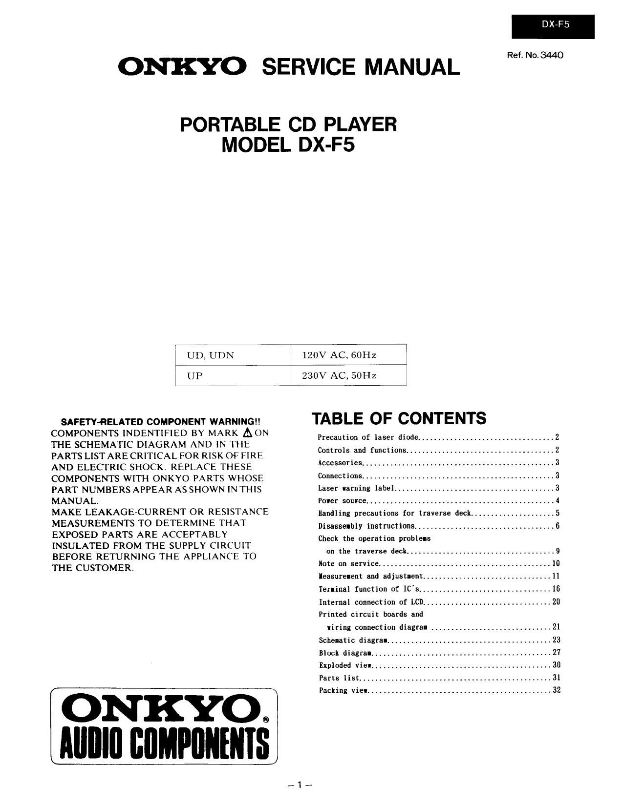
Onkyo DXF 5 Service Manual

This is the 29 pages manual for Onkyo DXF 5 Service Manual.
Read or download the pdf for free. If you want to contribute, please mail your pdfs to info@audioservicemanuals.com.

Page: 1 / 29
left right
Onkyo DXF 5 Service Manual

Extracted text from Onkyo DXF 5 Service Manual (Ocr-read)


Page 1

DX-F5

ONKYO SERVICE MANUAL W34

PORTABLE CD PLAYER
MODEL DX-F5

UD, UDN

120V AC, SOHZ

UP

230V AC, 50Hz

SAFETYRELATED COMPONENT WARNING
COMPONENTS INDENTIFIED BY MARK AON
THE SCHEMATIC DIAGRAM AND IN THE
PARTS LIST ARE CRITICAL FOR RISK OF FIRE
AND ELECTRIC SHOCK. REPLACE THESE
COMPONENTS WITH ONKYO PARTS WHOSE
PART NUMBERS APPEAR AS SHOWN IN THIS
MANUAL.

MAKE LEAKAGE-CURRENT OR RESISTANCE
MEASUREMENTS TO DETERMINE THAT
EXPOSED PARTS ARE ACCEPTABLY
INSULATED FROM THE SUPPLY CIRCUIT
BEFORE RETURNING THE APPLIANCE TO
THE CUSTOMER.

ONKYOQ
MIIIIII CflMPflIIfIIIS

TABLE OF CONTENTS

Precaution of laser diode .........

Controls and functions..
Accessories .....................
Connections .....................
Laser Iarning IabeL
Poner sou:ce,... ..............
Handling precautions for traverse deck.
Disasselbly instructions ............................... 6
Check the operation prohIeIs

on the traverse deck.. V V.9


Note on service .............
Ieasurenent and adjust-ant.
Terminal funcfion of [C's .....
Internal connection of LCD ......................... 20
Printed circuit boards and
Iiring connection diagral
Schematic diagral .......................
Block diagral ......
Exploded View ......
Parts list .........
Packing vie! .......

Page 2

DX-FS

.PRECAUTION OF LASER DIODE

CAUTION: This unit utilizes a class 1 laser.
when the unit is turned on:
Do not look directly into the pickup lens.

Do not use optical instruments to look at the pickup lens.
Do not adjust the preset variable resistor on the optical pickup.

Invisible laser radiation ls emitted from the optical pickup le\ns

it the optical pickup Is replaced, use the manufactures specified replacement pickup only.

1.
2.
3.
4. Do not disassemble the optical pickup unit.
5.
6.

Use of control or adjustments or periormance of procedures other than those specified herin
may result in hazardous radiation exposure.

I CONTROLS AND FUNCTIONS

Therunction rndiceied by the numbers with
black background (0) can also be anti»

Control Section

voted lrorn the Remote Control Transmit

ter. (See page 14,)

® Open Button (OPEN)

® Memory/Recall Button
(MEMORY/RECALL)
Use this button to play the program or
to confirm the program,

© Repeat Button (REPEAT)
Press this button to activate the repeat
mode. The repeat indicator illuminates.
Press again to cancel the repeat mode.
The repeat Indicator will no longer
iltuminate.

o Strip/Search Buttons
( H1 SKIP/SEARCH VD!)
Use these buttons to move the pickup
iorward and backward. or tr: hear the
disc sound as the pickup moves at high
speed while playing,

© Display
it this unit is used by AC adaptor or Car
adapter. the backlight oi the display will
be turned on.

© stop/Power 0" Button
(I STOP/POWER OFF)
0 Play/Pause Button
(5" PLAY/PAUSE)
When using rechargeable or dry cell
batteries, the Play/Pause Button oi the
Remote Control Transmitter will not
lunction it the main unit is turned aft.
Hold Switch (HOLD)
Functional buttons except lor Open
Button cannot be activated in the hold
stale.
aetore operating the lront panel bullori,
be sure to release the hold state.
Volume Control (VOLUME)
@ High FIIMIIDEE Selector
(HI-FlLTER/DBE)
Use the selector to listen to special
sound. (Headphones only)

Remote Control Transmitter Section

The function description oi pumms o. e is
as described under "Control Section" on
page 12-

- . "tut

® Headphone: JIGk (PHONES)

® Battery Compartment Cover
[bottom]

{9 Disc Holder

® Line Out Jack (LINE OUT)

Display Section

63 DO IN chk (DC IN Cl V)
® Plly Mode Selector (PLAY MODE)
@ Humane Sensor Jack
(REMOTE SENSOR)
Connect the included Remote Sensor
to use the unit by Remote Controlr
Transrnitter.

®._
@-
@-


RANDOM;
RESUME:

® Music Scan Indicator (IA. SCAN)
illuminates when the music scan play iS
operated, (by Remote Control Trans-
mitter only)

G) Random Play Indicator (RANDOM)
Illuminates when the random play
mode IS selected.

@ Resume Plly Indicator (RESUME)
illuminates when the resume play
mode is selected.

a: Track Display
Shows the number (up to 99) at the
current track

® Tithe Display
Shows the elapsed playing time at the
track being piayed.

0 Remote Control Tran-mission Mn-
m

Aim the transmission Window toward
the remote sensor oi the main unit
when operating the remote control.

m Numeric Button (1-10, is, >10)
These buttons are used to specify the
desired track number.

0 Music Scan Button (II. SCAN)
This button can be used to play the iirsi
part at each track In order

9 Clear Button (CLEAR)

Each time this button is pressed. the
last entry in the program sequence is
cancelled.


@ Repeat/A-E Repeat Play Indicator
(A o a)
Illuminates when the repeat button is
pressed (A-B repeat play is by the
Remote Control Transmitter only).

a Battery Cheek indicator r m l
Flashes on and oil when the batteries
are weak.

8 Charge Indicator ( u )
While charging. when the indicator
illuminates. playing lor approxrmately
1.5 hours can be operated. The indica-
tor wili turn oft, when the charging is
finished.

® Memory Indicator (M)
illuminates when the program play is
operated

0 Repeat Buttons (REPEAT)

The A-B repeat button can be used to
play the pomon at a disc between two
paints (A and B) chosen by you.

0 Stop Button (I STOP)

0 Output Button- (- OUTPUT +)
These button can be used to control
output level (lrorn -12 dB to D dB)

0 Recall Button (RECALL)

Press this button to corilirm the con-
tents or the program.

0 Memory Button (MEMORY)
Pressing this button initiates the pro-
grammed play mode. You can then
enter specific tracks usmg the numeric
buttons.

Page 9

DXvF5

.CHECKING THE OPERATION PROBLEMS ON THE TRAVERSE
DECK (OPTICAL PICKUP)

Make sure to follow the procedures below to check the operation problems of the traverse deck (optical pickup) before

replacing It.

(Procedure No.)

Replace the traverse deck only after the problem is Identified.

(Checking Points) (Cause)
Starting the reading operation
(TOG).
ls focus search
_.~° 2.22232...
(Check it lens moves
coll
up and down.)
YES
L.D
deterioration,
Does the laser turn on? NO or the position
lfitd th t t bl °"°
( lll 3°? e um a e turntable Is
w ro a 9) very low and
make contact
YES with the motor.
V NO Broken or
Tracking ON. -> shorted
tracking coll
YES
i NO Faulty PD
RF signal output. 7 (PHOTO
DETECTOR)

V

Traverse deck (optical
pickup) is normal.

OCheck electrical circuit.

'00 is not adjusted properly. Adjust CD again.
(1) Mechanical adjustment.
(2) Power supply voltage adjustment.
(3) Best eye adjustment (PD balance).

(4) Focus gain adjustment.
(5) Tracking gain adjustment.

(6) Focus oifset adjustment.

(7) Tracking ofiset adjustment.

(8) Tracking balance adjustment.
'Check for ilaws on disc or if it Is warped or not centered.

Refer to pages 13~15

_9_

(Testing Procedure)

Check it conductance
On both ends of coll with
the tester at about 30
ohms.

(The lens will slightly
move up and down
during the checking.)

- RF signal at the RF test
point is over 0.5Vp-p.
OCheck it the position of

the turntable Is not
very low and does not
make contact with the
motor.

Check if conductance
on both ends of coil with
the tester at about 30
ohms.

(The lens will slightly
move to the right or left
durlng the checking.)

Check It the output is
mlnimum 0.5Vp-p at the
test point.

Traverse deck (optical
pickup) is faulty.

X Replace traverse deck.

1