Onkyo DTR 4.6 TIPS TRICK Service Manual

This is the 34 pages manual for Onkyo DTR 4.6 TIPS TRICK Service Manual.
Read or download the pdf for free. If you want to contribute, please mail your pdfs to info@audioservicemanuals.com.

Page: 1 / 34
left right
Onkyo DTR 4.6 TIPS TRICK Service Manual

Extracted text from Onkyo DTR 4.6 TIPS TRICK Service Manual (Ocr-read)


Page 1

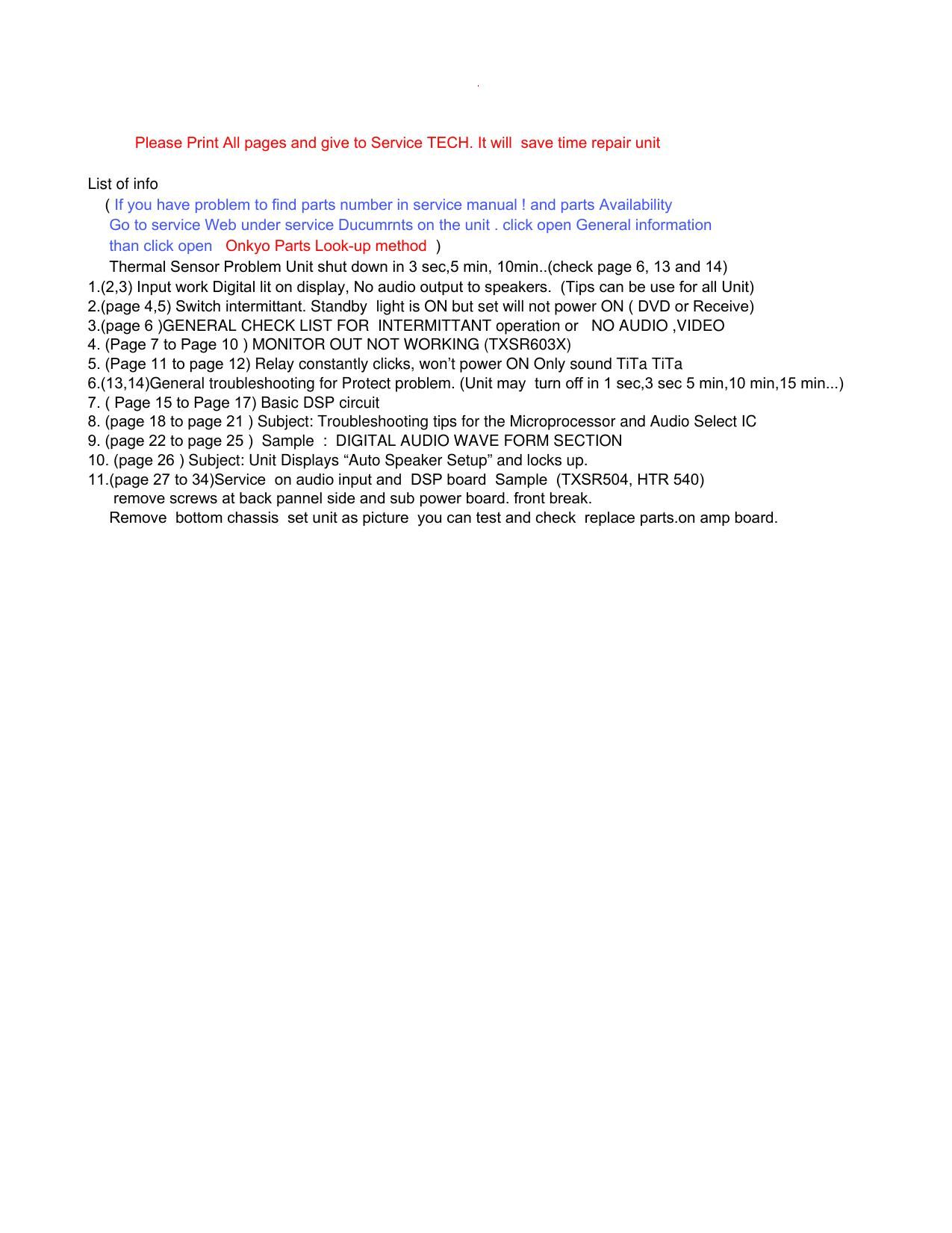
____ ___ ___ ___ ___ ___ ___ ___ ___ ___ ___ ___ ___ ___ ___ ___ ___ ___ ___ ___ ___ ___ ___ ___ ___ ___ ___ ___ _ CO NFI DENT IALITY NOTICE: This docu ment and the inf ormation it contains is intende d for th e exclusive use of Authorized ONKYO Servic e Centers and their e mployees. This docu ment may contain inform ation that is pr ivileged, confid ential and exem pt fr om disclosu re under applicable law and term s of the ONKYO Servic e Agree ment. Any d issemination, distri bution or copy ing of this docum ent and the inf ormation it contains is strict ly prohibited. CONFIDENTIAL TIPS & TRICKS 18 Park W ay, Upper Saddle River, NJ 07458 No . 20070724 Date: July 24, 2007 ________________________________ _____________________________ Model: DTR-4.6 (for ALL unit service info ) Subject: Input w ork Digital lit on displ ay, No audio output to speakers. Symptom : Use DVD RCA audio input, no au dio signal at Pin 4,5,6,7 at P3101B. (Check with Scope should have 2. 5 V DC with 0.2 V pp audio ** USE SCOPE TO CHECK ** Missing Out put from pin 8 to pin 15 on P3101B digital out Should be 0 V dc with 0.4 V pp) o v \ 0.4 v pp Soluti on: First check mi croprocessor Q701 control signal output. (5 V. ) 5 V R267, R268 VOLSTB and VOLCLK should have 5 V dc with 0 V 5 V pulse down to 0 V when adjust volume control. ( also at P3105B) R659 VOLDAT should have 0 V dc w ith 5 V pulse w hen adj volume.If low Remove pin 58,59,60 On Q 3003 if pulse w as low . To ch eck control signal back Up to 5 V. If control signal st ill low Q701 may be def. If yes have 5 V pulse Q3003 w as leaking Replace new IC. Next check +7 V and -“ 7 V pow er supply on Q3003 and Q3009. Remove XM Radio NARF-9688 and VIDEO Board NAVD-8657 . Check R3127 right side Reg Q3005 out pin 1 should be + 7 V. If low or +2.5 V Q3003 or Q3009 may be leaking. Remove pin 19 or VCC pin 39 on Q3009 and Check. Same as Q3006 ou t pin 3 ,Right side R3128 should be -“ 7 V. if low Replace def. Q3003 or Q3009. If control signal is good CD audio signal go in to Q 30\ 03, +7 v And -“ 7 V all good but no ADRT-,ADRT+ , ADLT- and ADLT+ audio out Replace Q3003 input select IC. \ 0.2 V pp Check next page !

Page 2

Page 5

READ ALL INFO IT WILL Help Y ou Save Time GENERAL CHECK LIST FOR INTERMITTANT operation or NO AUDIO ,VIDEO 1. What is idling current on each channel? Adjust and test. (If Idling adj. not change ! replaces surrounding transi stors and idling adj. resistor. 2. What was customer setup on speakers level? If too high reset unit and test. (It will over drive amp. When input signal go high unit will go protection) 3. What is each channel voltage from ID + to chasses ? Good Unit about 0.04V If a channel ID+ voltage much higher th an other. Replace the two input transistors (use same transistor) at driver circuit. It will drop this voltage down. 4. Use scope check do you have DC in any audio line ? ( When adj. volume up or down. Press and change input bottom) If yes find def. parts IC mutting transistors. 5. What is voltage on IPRO ( PROTEC T) Use scope ? Check transistors it may leak. 6. What is voltage on THERMAL line ? Check transi stors it may leak ( delay act. Some unit 5 sec, some unit act in 5 min. some 10 min or more. To turn unit to Thermal protection) Unit use TXSR XXX LM61CIZ Thermal Sensor. THRM line about 0.95V if unit turn on and 1.5V. Unit will go Thrmal protiction in 15 min. replace this sensor !! 7. Check power supply to all DSP IC . Use scope check voltage and noise!\ a. If unit audio work intermittent .Warm up lost audio. Check +5V,+3.3V and +2.5V if Low down and noise! Check Rag IC . Some unit is in amp board. Not in DSP board. Add more thermal joint compound and test. 8. When you have audio signal go in to a IC but no output. a. check you have good power DC supply to this IC ? b. do you have good control data from microprocessor to the IC ? c. If good on a. and b. than this IC is bad. (If problem a,b Repair a. or b. before replaces the ICs) 9. Video board problem? Check power supply to IC in board and Control signal from microprocessor! a. If power and control sign als all good. Switch IC not wo rking .replace this IC. b. If control signals bad! No video cont rol signals from microprocessor ? Replace microprocessor. ( If microprocesso r not available than replace PCB. some unit in DSP board ,some in input pre amp. or Microprocessor board.) 10. When you need help ! please give us all info power Voltage and where you lost signal ? an 11. Digital all channel work but volume\ control not working. Analog volume work. In set up Speaker o db volum\ e not work and some channel no sound. Use scope to check input sel IC\ at time adj volume V.CLK V DATA V.STB Good unit have 5V pluse. If V.DATA only have 3 V The\ input sel IC Damage. volume may work when unit cool. after IC heat up no control of volume. _CONFIDENTIALITY NOTICE: This document and the information it contains i\ s intended for the exclusive use of Authorized ONKYO Service Cente\ rs and their employees. This document may contain information that is privileged, confidential \ and exempt from disclosure under applicable law and terms of the ONKYO Service Agreement. Any dissemination, distribution or copyin\ g of this document and the information it contains i\ s strictly prohibited. 11

Page 20

Parts: Ref# Description Part Num ber Q7008 M icon, MP D784225GC-253-8BT 22242167R3 Q301 Audio Select IC, BD3817KS 22242117R3 X7001 Xtal, CSTCE12M 5G52-R0 3010361R2 ____ ___ ___ ___ ___ ___ ___ ___ ___ ___ ___ ___ ___ ___ ___ ___ ___ ___ ___ ___ ___ ___ ___ ___ ___ ___ ___ ___ _ CO NFI DENT IALITY NOTICE: This docu ment and the inf ormation it contains is intende d for th e exclusive use of Authorized ONKYO Servic e Centers and their employ ees. This docu ment may contain inform ation that is pr ivileged, confidential and exem pt fr om disclosur e under applicable law and ter ms of the O NKYO Service Ag reement. Any diss emination, distribution or copying of this docu ment and the inf ormation it contains is str ictly prohibited.