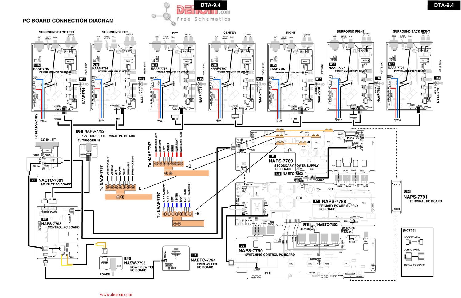
Onkyo DTA 94 Schematic

This is the 11 pages manual for Onkyo DTA 94 Schematic.
Read or download the pdf for free. If you want to contribute, please mail your pdfs to info@audioservicemanuals.com.

Page: 1 / 11
left right
Onkyo DTA 94 Schematic

Extracted text from Onkyo DTA 94 Schematic (Ocr-read)


Page 2

J
OPERATION CHECK-4 A O) F re E
OPERATION INDICATOR IN THE UNIT-1

(RED) @ D705

DC OUTPUT

D705 (DC OUTPUT) m NAAF-7797
This LEDTumed on when DC voltage is detected between speaker output ouTPuT

terminals XLH INPUT RCA +
Spealer output relay is turned off while having detected DC voltage SELECT
The relay will return automatically, if DC voltage output is lost.

(ORANGE) @ D710

MODULATOR
OPERATION

D710 (MODULATOR)

This LED shows the state of operation of an modulation circuiti
Immediately after a power supply injection, the light is switched on, and
this LED will put out the light, if operation of modulation circuit is started

(RED) (K) D751
TEMPERATURE
on

CURRENT

D751 (TEMPERATURE OR CURRENT)
This LED is turned on when an unusual temperature rise and unusual
over-current of an amplifier circuit are detected

NAPS-7793

Pumas Penna

(RED) @ D9805

POWER SUPPLY
WARNING

.ILmaA m

a; 9mm

D9805(POWER SUPPLY WARNING)
This LED is turned on when abnormalities arise in the
power supply circuiti

wwwidenom.com

Page 4

OPERATION CHECK-6

CAUTION IN THE CASE OF SPEAKER OUTPUT CHECK

The power amplifier circuit of DTA-9.4 is BTL system.

Therefore, in case you check speaker output, should be careful of the following point.
1 Do not connect the minus side OUTPUT terminal, and ground of the unit (Fig-1).

2 Do not connect minus of each OUTPUT terminals (Fig-2)

3 Cannot check with an oscilloscope between the plus side of an OUTPUT terminal, and Chassis GND. (Fig-3).

Fig-1
OUTPUT Oscilloscope
LEFT @
9
CENTER EB COD
(-3
RIGHT EB fi
9 Chassis GND of unit
Fig-2
OUTPUT
e D
9?
CENTER EB @
e |
RIGHT G.)
@-J
Fig-3
OUTPUT
E)
CENTER EB @
9
RIGHT ED
9 Chassis GND of unit

www.denom.com