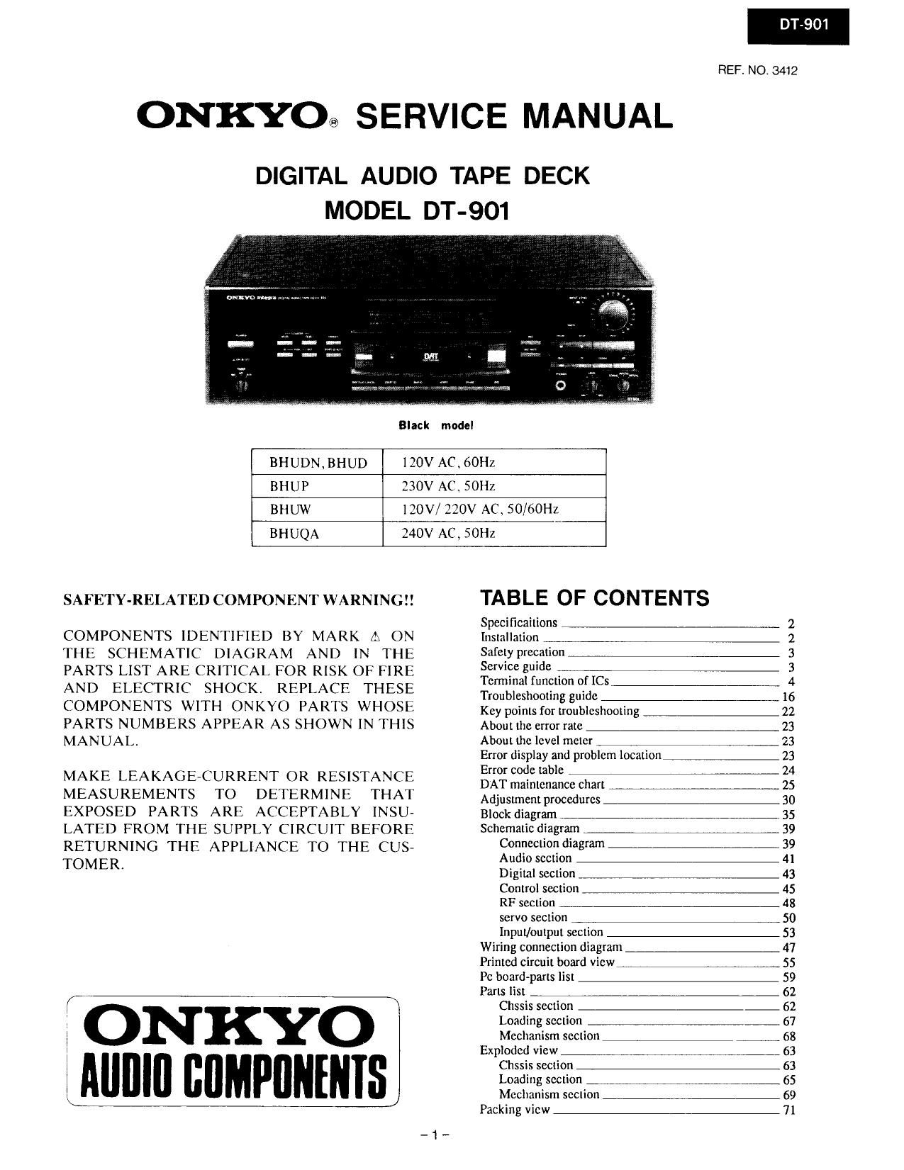
Onkyo DT 901 Service Manual

This is the 55 pages manual for Onkyo DT 901 Service Manual.
Read or download the pdf for free. If you want to contribute, please mail your pdfs to info@audioservicemanuals.com.

Page: 1 / 55
left right
Onkyo DT 901 Service Manual

Extracted text from Onkyo DT 901 Service Manual (Ocr-read)


Page 1

DT-901

REF. NO. 3412
ONKYO® SERVICE MANUAL
Black model
BHUDN,BHUD 120V AC. 60Hz
BHUP 230V AC, SOHZ
BHUW 120V/ 220V AC 50/60Hz
BHUQA 240V AC, SOHZ
SAFETY~RELATED COMPONE TWARNINGIl TABLE OF CONTENTS
Specificaitiens ,,,,,, 2
COMPONENTS IDENTIFIED BY MARK A ON Installation W_ 2
THE SCHEMATIC DIAGRAM AND IN THE Safely prchfliOflw 3
PARTS LIST ARE CRITICAL FOR RISK OF FIRE gem??? ;~~fiC--¥wiriw 3
AND ELECTRIC SHOCK, REPLACE THESE ngiéiéhfitififiifidc s - 1;
COMPONENTS WITH ONKYO PARTS WHOSE Key points for troubleshooting ____:; 22
PARTS NUMBERS APPEAR AS SHOWN IN THIS Abouttlie error rate 23
MANUAL. About. the level meter TfiW-i flw<___ 23
Error display and problem location 23
< i i V Error code table __.___ _ 24
MAKE LEAKAGE-CURRENT OR RESISTANCE DATmaintcnance chart Lifimfififii,i7,__25

MEASUREMENTS TO DETERMINE THA'I
EXPOSED PARTS ARE ACCEPTABLY INSU-
LATED FROM THE SUPPLY CIRCUIT BEFORE
RETURNING THE APPLIANCE TO THE CUS-
TOMERI

ONKYO
llilllllll [:lIMPlllllllls

Adjustment procedures
Block diagram ,,,77,,
Schematic diagram lm__
Connection diagram _
Audio section
Digital section
Control section


RF section ,____-___- 48
servo section ....... 4, v . 50
Input/output section - 53
Wiring connection diagram - 47
Printed circuit board view ,,,,,_7 ,,,,,,,,, .. 55
PC board Parts list _,7,,#,,______y-__ 62

Chssis section -

Loading section 7 , 7 ,,,,,,,,,,,,,,

Mechanism section
Exploded view

Chssis section

Loading section ifiii , , fiWiifi 65
Mechanism section ____.A_«- 69
Packing View -_- 71

Page 2

SPECIFICATIONS

Signal Format
Tape Recording System:
Sampling Frequencies:

Number of Quantization Bits:
Number of channels:

Audio (Analog recording and playback)

Frequency Response:
Dynamic Range:

8/ N Ratio:

Total Harmonic Distortion:
Wow & Flutter:

Input/Output jacks
Analog lnput Jacks
Lowest Input Level:
lnput Impedance:
Analog Output Jacks
Full-Scale Output Level:
Output Impedance:
Headphone Output:
Digital lnput Jacks:
Digital Output:

Mechanism

Head:

Cylinder Diameter:
Cylinder Rotational Speed:
Tape Speed:

Search Speed:
High-Speed Rewrnd Time:

General

Power Consumption:
External Dimensions:
Weight:

Rotating head system DAT

Recording: 48kHz, 44.1kHz, 32kHz (automatic digital input swrtching)
Playback: dBkHz, 44.1 kHz. 32kHz (automatic swrtching)

16-bit linear

Z-channel (stereo)

2H1 - 22.000Hz
SOdB or more
SOdB or more
0.005% or lower
Unmeasurable

450mV
20k ohms

2V

500 ohms

Max. 45mW 1- 45mW/32 ohms (most suitable impedance is 8 to 600 ohms)
Coaxial/75 ohms, Optical (switch equipped)

Optical

Amorphous/ferrite composite

30mm,1-3l16"

2000 r.p.m. (during recording and playback)

815mm (5/16") /sec.. 12.225mm (1/2") /sec. (automatic switching)
Max. 400 times normal

About 27 seconds (120 minute tape)

25W

455 (W) x 130 (H) X 371 (D) mm

17-15/16" (W) x 5-1/8 (H) x 14-11/16" (oi,
7.2Kg, 15.9 lbs.

Specifications and external appearance are subject to change Without notice because of product improvements

INSTALLATION

Avoid locations nearby tuners or television sets.
Since this Ul'llI uses high~trequency signals, placing it near a tuner or
teIeVIsion set may result in interference with the tuner/T V reception,
It this kind of audio or video interlerence is experienced. move the
DAT unit away from other AV components.

The some kind oi phenomenon may occur when using an indoor TV
antenna; whenever possible, use an outdoor antenna instead.

Precautions when using an indoor wire-strip
antenna (T-antenna) with FM tuner.
Separate the horizontal elements of the FM antenna at least 1,5 cm

from the tuner.

Indoor FM T-antenna"
Outdoor antenna a:


Horizontal element

Separate 1.5 m
0' more

FM tuner

Amplifier

DAT
Do not allow ieeder
wire to drape down
near DAT, (Hear View)

Do not allow the feeder wire from an indoor or outdoor FM antenna
todrape near the DAT unit. It excess feeder wire is present inside the
room, coil it up as tar as possible away from the DAT unit.

Page 24

DT-901

ERROR CODE TABLE

System control error code Mechanism control error code
Error code
(Note. 1) Processing Processin
0
(Note 2) Contents (Note 2) Contents
Test Mechanism mode switching
1 operation RSCP clock malfunction Unload lock
2 Te HSW clock malt nctl Unload Tape ioadin lock
operation u on D
3 Transmission Faulty transmission at the Unload Capsten unlock
omitted mechanism control
4 Unload Still protection during operation Unload Cylinder unlock
5 Unload Broken tape Unload Reel unlock
Sum oi reel cycles cannot be
6 Unload Faulty transmission 01 SP1 Unload measured.
In-cassetie rewind time
7 Unload exceeded
8 Unload Slack tape-up time exceeded.
9 Unload Tape Jamming (Supply side)
A Unload Tape Jamming (Take-up side)
a (-) Unload Gear does not engage.
C Tray stop inltlel tray setting not possible.
0 --- No error
FF (blank) No error -

Note 1: Display mode

Note 2: Processing when an error occurs

Test operation:
internal clock of the system control temporarily

E: Indicates that mode is the error rate display mode.

X1: System control error code

X2: Mechanism control error code

-24-

connects for operation.

Transmission omitted:

Transmission processing stopped.
Unload:
Tape is unloaded.