Onkyo DT 9000 Service Manual

This is the 53 pages manual for Onkyo DT 9000 Service Manual.
Read or download the pdf for free. If you want to contribute, please mail your pdfs to info@audioservicemanuals.com.

Page: 1 / 53
left right
Onkyo DT 9000 Service Manual

Extracted text from Onkyo DT 9000 Service Manual (Ocr-read)


Page 1

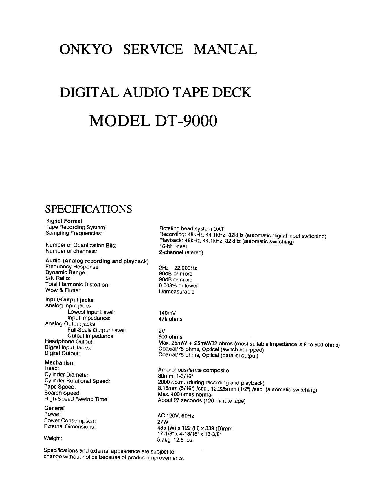
ONKYO SERVICE MANUAL

DIGITAL AUDIO TAPE DECK
MODEL DT-9000

SPECIFICATIONS

Signal Format
Tape Recording System:
Sampling Frequencies:

Number of Quantization Bits:
Number of channels:

Audio (Analog recording and playback)
Frequency Response:

Dynamic Range:

S/N Ratio:

Total Harmonic Distonlon:

Wow & Flutter:

Input/Output jacks
Analog input jacks
Lowest input Level:
Input impedance:
Analog Output jacks
Full-Scale Output Level:
Output impedance:
Headphone Output:
Digital input Jacks:
Digital Output:

Mechanism

Head:

Cylinder Diameter:
Cylinder Rotational Speed:
Tape Speed:

Search Speed:
High-Speed Rewind Time:

General

Power:

Power Consumption:
External Dimensions:

Weight:

Rotating head system DAT

Recording: 48kHz, 44.1kHz, 32kHz (automatic digital input switching)
Playback: 4BkHz, 44:1kHz, 32kHz (automatic switching)

16-bit linear

2-channel (stereo)

2H2 - 22:000Hz
90dB or more
90dB or more
0.008% or lower
Unmeasurable

140mV
47k ohms

2V

600 ohms

Maxt 25mw + 25mW/32 ohms (most suitable impedance is 8 to 600 ohms)
Coaxial/75 ohms, Optical (switch equipped)

Coaxial/75 ohms, Optical (parallel output)

Amorphous/ferrite composite

30mm, 1-3/16'

2000 rpm. (during recording and playback)

815mm (5/16) /sec., 12,225mm (1/2") /sec. (automatic switching)
Max. 400 times normal

About 27 seconds (120 minute tape)

AC 120v, 60Hz
27w

435 (W) x 122 (H) x 339 (D)mm
17-1/8' x 4.13/16" x 13-3/8"
57kg, 12.6 lbs.

Specifications and external appearance are subject to
change without notice because of product improvements.

Page 2

DT«9000

3

I EXPLODED VIEWS

/

- Cablnei Ind chasals par

Page 14

. DT-9000

5. ADC Offset Adjustment

This adjustment is necessary when the indication of
the level meter is abnormal.

1. Load a blank tape into the deck and place the deck 2. Adjust VR451 (Lch) and VR452 (Rch) so that the
in REC-PAUSE mode. indication of the level meter is not illuminated.

6. BOTIEOT Detection Sensitivity Verification and Adjustment

1. Make sure that the tape stops with the leader

portion (the beginning and ending portion). BOTEOT "9)

X If the tape does not stop at the leader, make -" 5V
adjustment by following procedure outlined

below. >

(Dlnsert a blank tape into the tape compartment of CN53 ' W
the set and press the playback button at the end

of the tape. ,»

@Set up the oscilloscope and connect as shown CNS" 6 5"
below.
-- - c ----- - ---- 1v
(SH-1 CH-2 0V
ON54 magnetic substance
Test point 6}(BOTIEOD CNSG l ____ 5V
(2/ (magnetic substance)
Volts/Div. c.2v 0.2V
CN58 1,, av
TimeIDiv. 2msec.
Delay -

_ CN54 :3» W- 5v
Trig. CH'Z _________________ 4V
Ac-GND-DC AC J DC
Adjustment point vam °V

©Adiust the amplitude oi waveform to less than
1V at the magnetic substance and more than 4V
at the leader on VR271.

7. Linearity Adjustment

Caution: The post rollers are used for linearity adjustment. Gradually change the post roller heights until the RF
signal envelope becomes rectangular,

l
1 Post roller Post roller
Post rolls! I
adjusting '
screwdriver I
1 Do not touch the
A 4 guide roller.
[
m Do not touch the
guide roller.
Tape

Page 16

)T-9000

.TERMINAL FUNCTION OF ICS

- IC101 (AN703DSE2): RF AMP.

Pin IIO Pin IIO
No. Mark Division Function N a. Mark III I ion Function
1 Von 1 I Power supply terminal 24 HSW I Head switching signal
2 ACH FB 0 Playback feed back signal (A on) 25 AR IFISEL I Eggs. connected to power
a ACH IN I Playback amp. signal (A on)
Recordinglpiayback select
4 GND 1 - GND terminal 25 RPSEL ' signal (REC: ".H PLAY: '1")
5 BCH IN I Playback amp. signal (Bah) 27 50 OUT 0 Equalization signal
6 BCH FB 0 Playback feed back signal (Ben) 28 E0 IN 3
7 AREC POM 29 E0 IN 2 i Equalization amp. signal
8 AREC PLT 30 £0 IN 1
9 AREC ATF Equalization amplitude drive
I RF recording level adj. terminal 31 BF REG ' terminal (Sch)
10 BFIEC ATF
Equalization phase drive
11 anec PLT 32 5 PHASE ' terminal (Bell)
12 BREC PCM 33 B GAIN . (Esqg'nllzatlon gain drive terminal
13 REC ONT 1 I Track pitch signal
Equalization amplitude drive
14 REC ONT 2 l ATF area dei. signal 34 AF REG | terminal (Ach)
15 SRRF IN I Recording signal Equalization phase drive
35 A PHASE ' terminal (Ann)
16 GND 2 - GND terminal
Equalization gain drive terminal
17 VREF O Relerance voltage terminal 36 A GAIN I (Ach)
(Not used, open)
37 SV RF 0 Playback signal
18 AREC OUT 0 Recording signal (Ach)
38 GND 3 - GND terminal
19 SREC OUT 0 Recording signal (Bell)
39 A INT I Playback amp. signal (Ach)
20 BTL REC 0 Recording control signal
40 3 INT I Playback amp. signal (Ben)
21 V03 2 I Power supply terminal
41 3 INT IN 0 Playback amp. signal (Bch)
Recording drive terminal
22 REC 0 O (REC: H") 42 A INT IN 0 Playback amp. signal (Ach)
Playback drive terminal
PLAY ON 0 (PLAY: H"l