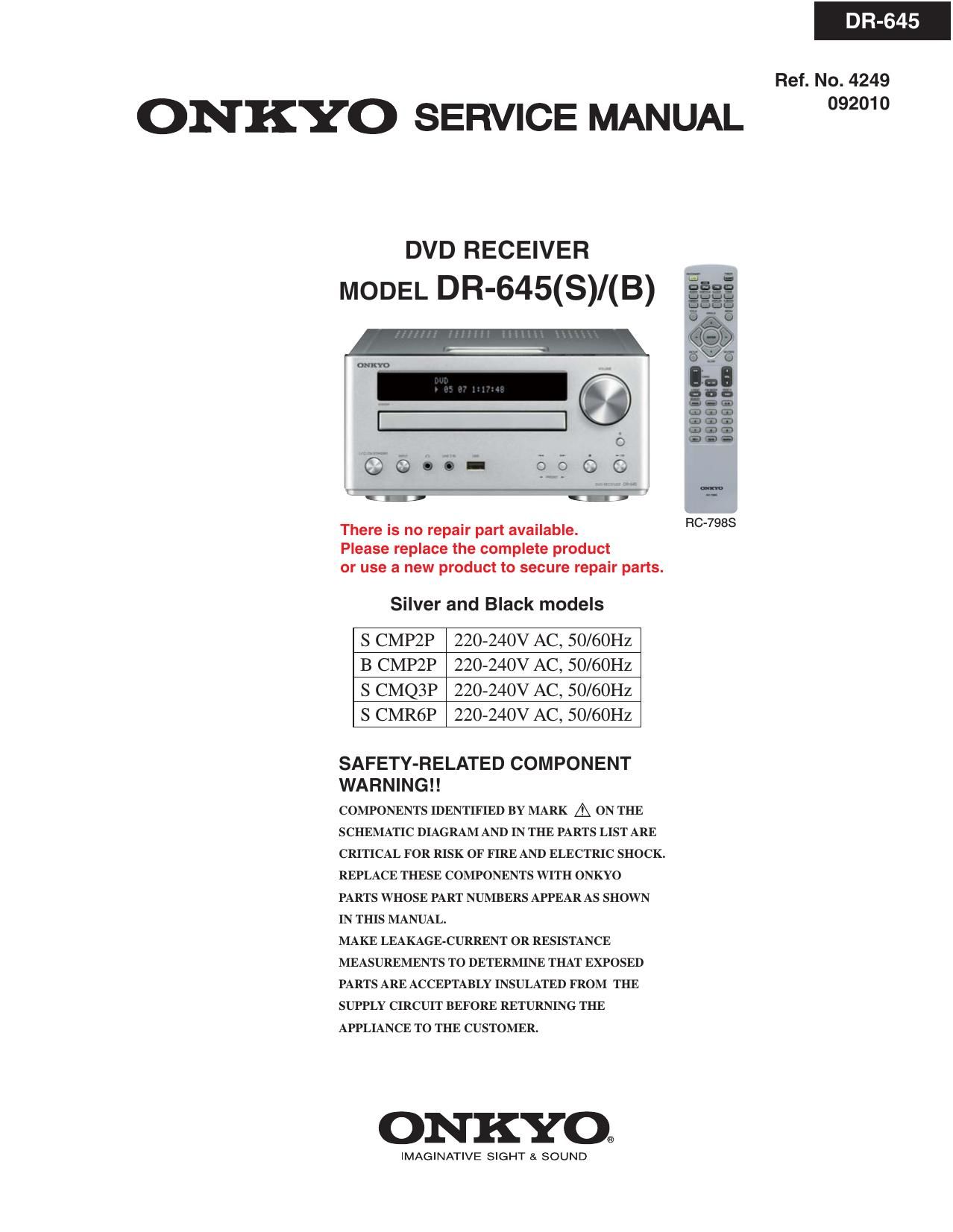
Onkyo DR 645 Service Manual

This is the 28 pages manual for Onkyo DR 645 Service Manual.
Read or download the pdf for free. If you want to contribute, please mail your pdfs to info@audioservicemanuals.com.

Page: 1 / 28
left right
Onkyo DR 645 Service Manual

Extracted text from Onkyo DR 645 Service Manual (Ocr-read)


Page 1

DR-645
Ref. No. 4249

ONKYO SERVICE MANUAL 2"

DVDRECHVER
MODEL DR-645(S)/(B)

0|
I
OI

i " H
_ 3::
Gas
:1 , 2:2
0 666

5663i :15: O
Pic-7983

There is no repair part available.
Please replace the complete product
or use a new product to secure repair parts.

Silver and Black models

S CMPZP 220-240V AC, 50/60Hz
B CMPZP 220-240V AC, 50/60Hz
S CMQ3P 220-240V AC, 50/60Hz
S CMR6P 220-240V AC, 50/60Hz

SAFETY-RELATED COMPONENT
WA R N I N G ! !

COMPONENTS IDENTIFIED BY MARK A ON THE
SCHEMATIC DIAGRAM AND IN THE PARTS LIST ARE
CRITICAL FOR RISK OF FIRE AND ELECTRIC SHOCK.
REPLACE THESE COMPONENTS WITH ONKYO
PARTS WHOSE PART NUMBERS APPEAR AS SHOWN
IN THIS MANUAL.

MAKE LEAKAGE-CURRENT 0R RESISTANCE
MEASUREMENTS TO DETERMINE THAT EXPOSED
PARTS ARE ACCEPTABLY INSULATED FROM THE
SUPPLY CIRCUIT BEFORE RETURNING THE
APPLIANCE TO THE CUSTOMER.

ONKYO®

IMAGINATIVE SIGHT SI SOUND

Page 2

Contents page

* Measurement Setup ....................................................................................................... 1-1
* Items Safety Attention .......................................................................................... 2-1 to 2-2
* Instruction On CD Playability ............................................................................... 3-1 to 3-2
* Electrical Specificaction ....................................................................................... 4-1 to 4-2
* Block Diagram ................................................................................................................ 5-1
* Wiring Diagram ............................................................................................................... 6-1
* ECO Power and Speaker Output Board

Circuit Diagram ......................................................................................................... 7-1

Layout Diagram ........................................................................................................ 7-1
* Display and Key Board

Circuit Diagram ......................................................................................................... 7-2

Layout Diagram ........................................................................................................ 7-3
* Tuner Board

Circuit Diagram ......................................................................................................... 7-4

Layout Diagram ........................................................................................................ 7-4
* IPOD Board

Circuit Diagram ......................................................................................................... 7-5

Layout Diagram ........................................................................................................ 7-5
* USB and Headphone Board

Circuit Diagram ......................................................................................................... 7-6

Layout Diagram ........................................................................................................ 7-6
* Decoder Board

Circuit Diagram .................................................................................................. 7-7 to 7-13

Layout Diagram ........................................................................................................ 7-14
*Explode View Diagram ................................................................................................... 8-1
* Factory Part List ....................................................................................................... 9-1 to 9-7

* Revision List ............................................................................................................. 10-1

Page 3

Measurement Setup

Tuner FM

Bandpass

250HZ-15kHZ
e.9. 7122 707 48001

DUT

RF Generator
e.g. PM5326

LF Voltmeter
e.g. PM2534

SIN and distortion meter
9.9 Sound Technology snmoa

sQ

O O

Use a bandpass filter to eliminate hum (50Hz, 100Hz) and disturbance from the pilottone (19kHz, 38kHZ).

Tuner AM (MW,LW)

Bandpass

250HZ~15kHZ
9.9. 7122 707 48001

LF Voltmeter
so PM2534

RF Generator
9.9. PM5326

Frame aerial
e g. 7122 707 89001

SIN and distortion meter
e.g. Sound Technology $117005

eg

0 O

To avoid atmospheric interference all AM-measurements have to be carried out in a Faraday's cage.
Use a bandpass filter (or at least a high pass filter with 250HZ) to eliminate hum (50Hz, 100Hz).

CD

Use Audio Signal Disc SBC429 4822 397 30184
(replaces test disc 3)

DUT

L

K
R-o o o

SIN and distortion meter
9.9. Sound Technology STlmoa

O O

LEVEL METER
e,g. Sennheiser UPM550
wlth FF-filter

Recorder

Use Universal Test Cassette Cr02 SBC419 4822 397 30069
or Universal Test Cassette Fe SBC420 4822 397 30071

DUT
LF Generator L
9.9. PMsllo 4K0
R_o o

O

SIN and distortion met
e.g. Sound Technology STl 7o

O

O

LEVEL METER
6,9. Sennheiser UPM550
with FF-filter