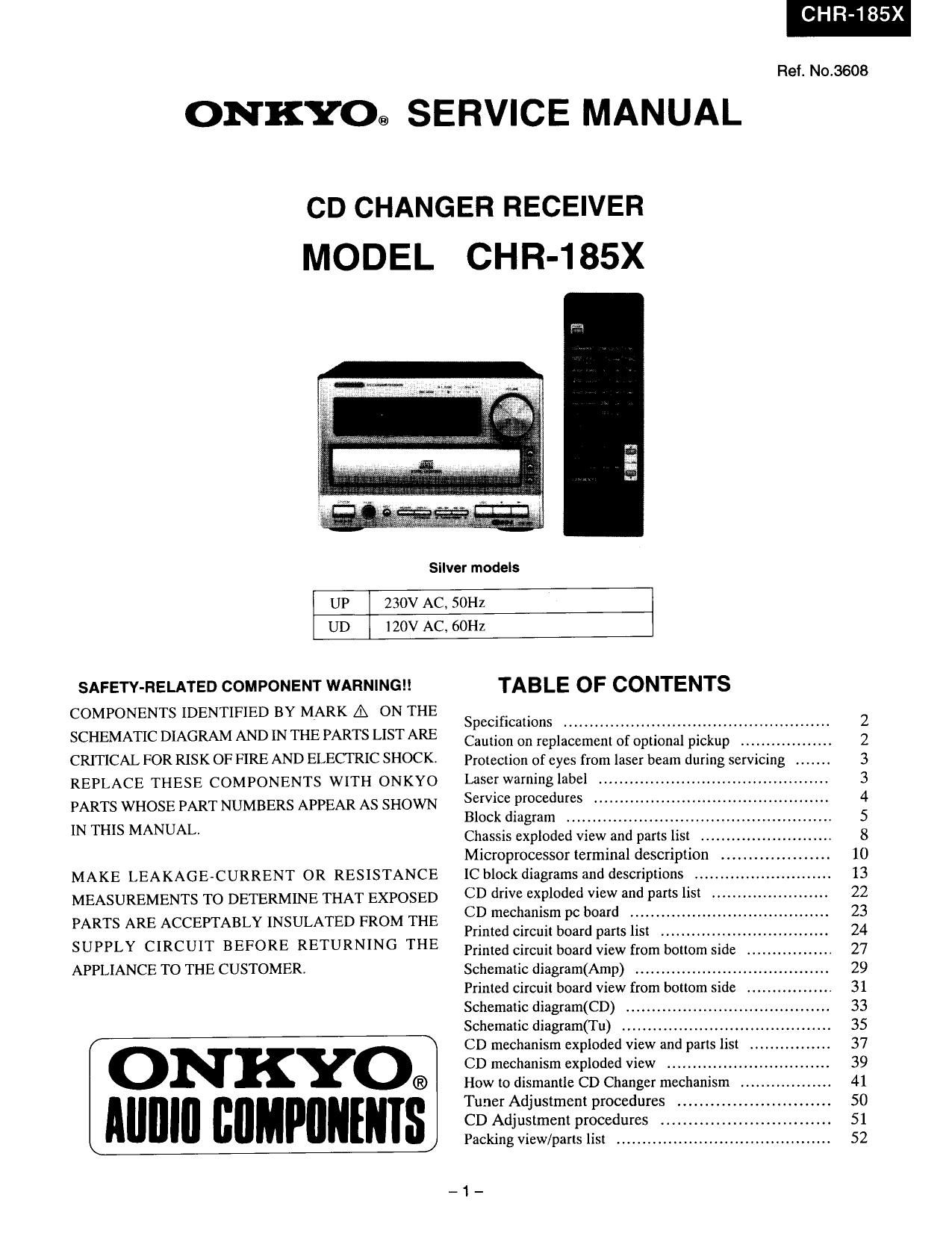
Onkyo CR 185 X Service Manual

This is the 34 pages manual for Onkyo CR 185 X Service Manual.
Read or download the pdf for free. If you want to contribute, please mail your pdfs to info@audioservicemanuals.com.

Page: 1 / 34
left right
Onkyo CR 185 X Service Manual

Extracted text from Onkyo CR 185 X Service Manual (Ocr-read)


Page 2

CHR-185

SPECIFICATIONS

AMP SECTION

Power Output:
US model:

Other models:

Dynamic Power:

Total Harmonie Distortion:

1M Distortion:
Damping Factor:

Sensitivity and Impedance:

Frequency Response:
Tone Control:

Single-to-Noise Ratio:
Muting

FM Tuner section

Tuning Range:
US model:
Other models:
Usable Sensitivity:

50 dB Quieting Sensivity:

Capture Ratio:
Image Rejection Ratio:

IF Rejection Ratio:
Signalito-Noise
Ratio:
Selectivity:
US model:
Other models:
Harmonic Distortion:

Frequency Response:
Stereo Separation:

Stereo Threshold:

CAUTION ON REPLACEMENT OF OPTIONAL PICKUP

20 watts per channel min. RMS into 4
ohms hoth channel driven at 1 kHz no
more than 0.2% total harmonic distortion
2 x 20 watts at 4 ohms 1 kHz DIN

2 x 15 watts at 8 ohms 1 kHz DIN

2 x 25 watts at 4 ohms EIAJ

2 x 24 watts at 4 ohms

2 x18 watts at 8 ohms

0.2 % at rated power

0.2 % at rated power

40 at 8 ohms

TAPE / MD PLAY : 150 mV. 50 kohms
LINE 1N : 150 mV, 50 kohrns

10 to 50,000 Hz : +0 / -3dB

Super BASS : + 9.5 dB at 55 Hz

BASS : t 10 dB at 100 Hz
TREBLE1110 dB at 10,000 Hz

TAPE: 100 dB (I'HF A)

-m dB

87.9 to 107.9 MHz (200 kHz steps)

87.50 to 108.00 MHz (50 kHz steps)

Mono 12.8 dBf. 1.2 uV (75 ohms IHF)
1.0 11V (75 ohms DIN)

Stereo 18.0 dBf, 2.2 LIV (75 ohms IHF)
25.0 W (75 ohms DIN)

Mono 18.8 dBf. 2.4 pV (75 ohms)

Stereo 38.8 dBf,24.0 ttV (75 ohms)

2.0 dB

US model: 41) dB

Other models: 85 dB

90 dB

Mom) 73 dB. IHF

Stereo 67 dB. IHF

55 dB

SOdB DIN (+ l- 300 kHz at 40 kHz devi.)
Mono 1.0 %

Stereo 1.5 %

30m 15,000Hz (+/- 1.5 dB)

35 dB at 1.000 Hz

25 dB at 100 to 10,000 Hz

FM : 17.2 dBf, 2.0 uV (75 ohms)

CD SECTION

Signal Readout System:
Reading Rotation:

Linear Velocity:

Error Correction System:

D I A Converter:

Di gital Filter:
Number of Channels:
Frequency Response:

General

Power Supply:

Power Consumption:
Dimensions:

Weight:

Optical non-contact

About 500 - 200 r.p.m. (constant linear
velocity)

[.2 - 1.4 ml s

Cross lnterleave Read Solomon code

1 bit

352.8 kHz 8 times over sampling

2 (stereo)

5 Hz - 20 kHz

AC 230 V, 50 Hz

AC 120 V. 60 Hz

55 W

185Wx 131 Hx 378Drnm
(75/16" X 53/16" x 14-7/8")
50 kg (11.0 lbs)

Specifications and features are subject to change without notice.

The laser diode in the optical pickup block is so sensitive to
static electricity, surge current and etc, that the components
are liable to be broken down or its reliability remarkably
deteriorated.

PRECAUTIONS

During repair, carefulley take the following precautions.
(The following precautions are included in the service parts.)

1.Gmund for the work-desk.
Place a conductive sheet such a a sheet of copper (witch
inpedance lower than lOMQ) on the work.desk and
place the set on the conductive sheet so that the chassis.
2.Gmunding for the test equipment and tools.
Test equipment and toolings should be grounded in order
that their ground level is the same the ground of the
power source.

3.Gmunding for the human body.
Be sure to put on a wrist-strap for grounding whose other
end is grounded.
Be particulary carful when the workers wear synthetic
fiber clothes. or air is dry. .

4.Select a soldering iron that permits no leakage and have
the tip of the iron well- grounded.

5.Do not check the laser diode terminals with the probe of
a circuit tester or osilloscope.

-2-

Page 3

CHR-185X

PROTECTION OF EYES FROM LASER BEAM DURING SERVICING

This set employs a laser. Therefore, be sure to follow
carefully the instructions below when servicing.

WARNING I!

WHEN SERVICING, DO NOT APPROACH THE
LASER EXIT WITH THE EYES TOO CLOSELY.
IN CASE IT IS NECESSARY TO CONFIRM LASER
BEAM EMISSION, BE SURE TO OBSERVE FROM
A DISTANCE OF MORE THAN 30cm FROM THE
SURFACE OF THE OBJECTIVE LENS ON THE
OPTICAL PICK-UP BLOCK.

LASER WARNING LABELS

There labels are located on the mechanism.

I. ernlnl Ilbk
This label is located on the chassis.

GEII -|NVl5lBLE LASER LRADDIATION
WHEN OEEIIA DKINTERLOC
DEFEATED AVOID DIRECT EXPOSIURE To BEAM

IITIUII -HAZARDOUS LASER AND
ELECTROMAGNETIC RADIATION WHEN OPEN
AND INTERLOCK DEFEATED,

[III -RAYONNEMENT LASER

ET ELECTROMAGNEIIOUE DANGEREUX
RUVERT AVEC L ECLENCHEMENT DE SECIURITE

2. Clue l label
This label is located on the left side of top covert

LUOKAN 1
"CLASS 1 LASER LASERLAITE
PRODUCT" KLASS 1

LASER APPARAT

Laser Diode Properties

- Material: GaAlAs

- Wavelength: 760-800nm

~ Emission Duration: continuous

- Laser output: max. 0.5mW*

* This output is the value measure at a distance about 1.8mm
from the objective lens surface on the Optical pick-up
Blocki