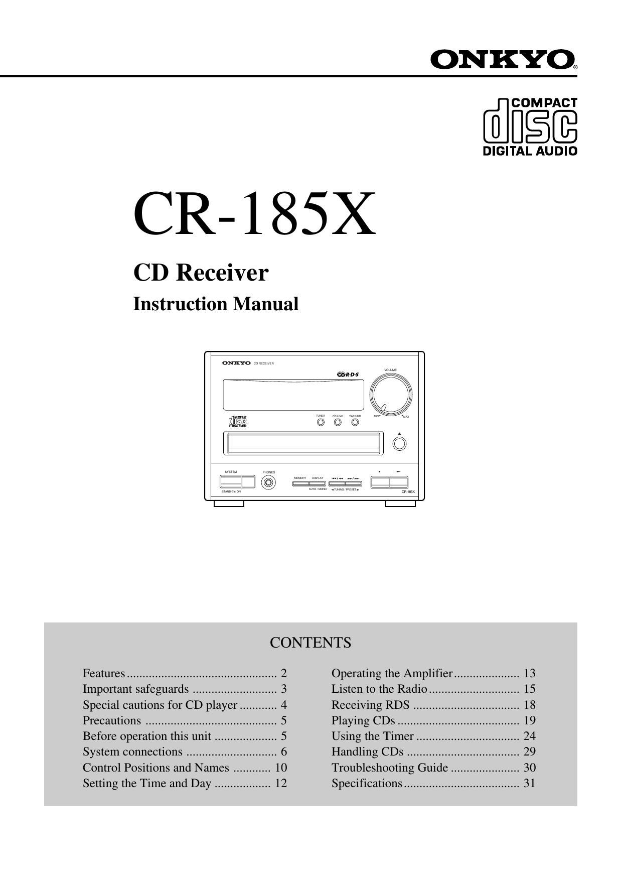
Onkyo CR 185 X Owners Manual

This is the 32 pages manual for Onkyo CR 185 X Owners Manual.
Read or download the pdf for free. If you want to contribute, please mail your pdfs to info@audioservicemanuals.com.

Page: 1 / 32
left right
Onkyo CR 185 X Owners Manual

Extracted text from Onkyo CR 185 X Owners Manual (Ocr-read)


Page 1

2ATTENTION FOR BRITISH MODELReplacement and mounting of an AC plug on the power supply cord of this unit should be performed only by qualified service personnel. IMPORTANT: The wires in the mains lead are coloured in accordance with the following code: Blue: Neutral Brown: Live As the colours of the wires in the mains lead of this appliance may not correspond with the coloured markings identifying the terminals in your plug, proceed as follows: The wire which is coloured BLUE must be connected to the terminal in the plug which is marked with the letter N or coloured BLACK. The wire which is coloured BROWN must be connected to the terminal in the plug which is marked with the letter L or coloured RED. IMPORTANT A 5 amp fuse is fitted in this plug. Shoud the fuse need to be replaced please ensure that the replacement fuse has a rating of 5 amps and that it is approved by ASTA or BSI to BS 1362. Check for the ASTA mark or the BSI mark on the body of the fuse. IF THE FITTED MOULDED PLUG IS UNSUITABLE FOR THE SOCKET OUTLET IN YOUR HOME THEN THE FUSE SHOULD BE REMOVED AND THE PLUG CUT OFF AND DISPOSED OF SAFELY. THERE IS A DANGER OF SEVERE ELECTRICAL SHOCK IF THE CUT OFF PLUG IS INSERTED INTO ANY 13 AMP SOCKET. If in any doubt please consult a qualified electrician.Declaration of ConformityWe, ONKYO EUROPE ELECTRONICS GmbH INDUSTRIESTRASSE 20 82110 GERMERING, GERMANY declare in own responsibility, that the ONKYO product described in this instruction manual is in compliance with the corresponding technical standards such as EN55013, EN55020, EN61000-3-2, -3-3 and EN60065 GERMERING, GERMANY ONKYO EUROPE ELECTRONICS GmbHK.OTSUFOR U.S.A. MODELNote to CATV system installer:lThis reminder is provided to call the CATV system installerÕs attention to Section 820-40 of the NEC which provides guide- lines for proper grounding and, in particular, specifies that the cable ground shall be connected to the grounding system of the building, as close to the point of cable entry as practical.FOR CANADIAN MODEL POUR LE MODELE CANADIENlFor models having a power cord with a polarized plug.CAUTION: TO PREVENT ELECTRIC SHOCK, MATCH WIDE BLADE OF PLUG TO WIDE SLOT, FULLY INSERT.lSur les modles dont la fiche est polarisŽe.ATTENTION: POUR ƒVITER LES CHOCS ƒLECTRI- QUES, INTRODUIRE LA LAME LA PLUS LARGE DE LA FICHE DANS LA BORNE CORRESPONDANTE DE LA PRISE ET POUSSER JUSQUÕAU FONDFOR EUROPEAN MODELThank you for purchasing the Onkyo CR-185X CD Receiver. Please read this manual thoroughly before making connections and operating the unit. Following the instructions in this manual will enable you to obtain optimum performance and listening enjoyment from your new CD Receiver. Please retain this manual for future reference.Featuresn20 Watts Per Channel into 4 ohms, 1kHz, DIN nExceptionally Compact nUnique CD Player and Receiver Combination n4-Ohm Drive Ñ extremely uncommon for a component this size Ñ the result of superior thermal engineering and high quality parts; can handle the widest variety of speakers without distortion or cutting off nOversized, High-Current Power Transformer with heavy- duty shielding minimizes flux leakage and provides better dynamic impact (strong bass, clear transients, subtlety in music) nOptical Digital Output for optimum digital-to-digital perform- ance when connected to a DAT deck, MiniDisc recorder, amp or receiver with direct digital inputs nLine-In Input for quick, easy connection to a TV, VCR or any other analog component nCostly Discrete Output Stage Circuits for superior sonic characteristics, enhanced cooling and high-current handling capability nSolid Aluminum Front Panel for added value and long-term elegance Ñ further evidence of OnkyoÕs attention to detail nRI Compatible Full-Function Remote with logical layout to enhance operation easeSupplied accessory Remote control (1) Dry batteries UM-3 (2) FM indoor antenna (1) 75/300 ohm antenna adapter (1) (supplied with models other than the European model)

Page 2

3Important safeguards1.Read Instructions Ð All the safety and operating instructions should be read before the appliance is operated. 2.Retain Instructions Ð The safety and operating instructions should be retained for future reference. 3.Heed Warnings Ð All warnings on the appliance and in the operating instructions should be adhered to. 4.Follow Instructions Ð All operating and use instructions should be followed. 5.Water and Moisture Ð The appliance should not be used near water - for example, near a bathtub, washbowl, kitchen sink, laundry tub, in a wet basement, or near a swimming pool, and the like. 6.Carts and Stands Ð The appliance should be used only with a cart or stand that is recommended by the manufacturer. 6A. An appliance and cart combination should be moved with care. Quick stops, excessive force, and uneven surfaces may cause the appliance and cart combination to overturn. 7.Wall or Ceiling Mounting Ð The appliance should be mounted to a wall or ceiling only as recommended by the manufacturer. 8.Ventilation Ð The appliance should be situated so that its location or position does not interfere with its proper ventilation. For example, the appliance should not be situated on a bed, sofa, rug, or similar surface that may block the ventilation openings; or if placed in a built-in installation, such as a book case or cabinet that may impede the flow of air through the ventilation openings, there should be free space of at least 20 cm and open up behind the appliance. 9.Heat Ð The appliance should be situated away from heat sources such as radiators, heat registers, stoves, or other appliances (including ampli- fiers) that produce heat. 10.Power Sources Ð The appliance should be connected to a power supply only of the type described in the operating instructions or as marked on the appliance. 11.Polarization Ð If the appliance is provided with a polarized plug having one blade wider than the other, please read the following information: The polarization of the plug is a safety feature. The polarized plug will only fit the outlet one way. If the plug does not fit fully into the outlet, try reversing it. If there is still trouble inserting it, the user should seek the services of a qualified electrician. Under no circumstances should the user attempt to defeat the polarization of the plug. 12.Power-Cord Protection Ð Power-supply cords should be routed so that they are not likely to be walked on or pinched by items placed upon or against them, especially near plugs, convenience receptacles, and the point where they exit from the appliance. 13.Cleaning Ð The appliance should be cleaned only as recommended by the manufacturer.14.Power Lines Ð An outdoor antenna should be located away from power lines. 15.Nonuse Periods Ð The power cord of the appliance should be unplugged from the outlet when left unused for a long period of time. 16.Object and Liquid Entry Ð Care should be taken so that objects do not fall and liquids are not spilled into the enclosure through openings. 17.Damage Requiring Service Ð The appliance should be serviced by qualified service personnel when: A. The power-supply cord or the plug has been damaged; or B. Objects have fallen, or liquid has been spilled into the appliance; or C. The appliance has been exposed to rain; or D. The appliance does not appear to operate normally or exhibits a marked change in performance; or E. The appliance has been dropped, or the enclosure damaged. 18.Servicing Ð The user should not attempt to service the appliance beyond that described in the operating instructions. All other servicing should be referred to qualified service personnel. 19.Outdoor Antenna Grounding Ð If an outside antenna is connected to the receiver, be sure the antenna system is grounded so as to provide some protection against voltage surges and built up static charges. Article 810 of the National Electrical Code, ANSI/NFPA 70, provides information with regard to proper grounding of the mast and supporting structure, grounding of the lead-in wire to an antenna discharge unit, size of grounding conductors, location of the antenna-discharge unit, con- nection to grounding electrodes, and requirements for the grounding electrode. See Figure 73.1.FIGURE 73.1: EXAMPLE OF ANTENNA GROUNDING AS PER NA- TIONAL ELECTRICAL CODEGROUND CLAMP ELECTRIC SERVICE EQUIPMENT POWER SERVICE GROUNDING ELECTRODE SYSTEM (NEC ART 250, PART H)GROUND CLAMPSGROUNDING CONDUCTORS (NEC SECTION 810-21)ANTENNA DISCHARGE UNIT (NEC SECTION 810-20)ANTENNA LEAD IN WIRE NEC - NATIONAL ELECTRICAL CODE S2898AlThe lightning flash with arrowhead symbol, within an equilateral triangle, is intended to alert the user to the presence of uninsulated Òdangerous voltageÓ within the productÕs enclosure that may be of suffi- cient magnitude to constitute a risk of electric shock to persons.lThe exclamation point within an equilateral triangle is intended to alert the user to the presence of important operating and maintenance (servicing) instructions in the literature accompanying the prod- uct.S3125APORTABLE CART WARNINGÒWARNINGÓÒTO REDUCE THE RISK OF FIRE OR ELECTRIC SHOCK, DO NOT EXPOSE THIS APPLIANCE TO RAIN OR MOIS- TURE.ÓCAUTION:ÒTO REDUCE THE RISK OF ELECTRIC SHOCK, DO NOT REMOVE COVER (OR BACK). NO USER-SERVICEABLE PARTS INSIDE. REFER SERVICING TO QUALIFIED SERV- ICE PERSONNEL.ÓWARNINGRISK OF ELECTRIC SHOCK DO NOT OPENRISQUE DE CHOC ELECTRIQUE NE PAS OUVRIRAVIS

Page 27

28Using the sleep setting The sleep setting can power off the system after a specified time period has passed. 1. Play what you would like to listen to (CD, tape, radio broadcast, MD or Line). 2. Press the SLEEP button repeatedly to set the desired sleep time (90 to 10 in 10 minute intervals). After the specified time has passed, the power will be switched off automatically. ¥ To check the remaining time, press the SLEEP button. ¥ During CD dubbing, the power will not be switched off until the dubbing is fin- ished, even if the sleep time passes. Cancelling the sleep setting Press the SLEEP button repeatedly until the sleep setting is turned off (nothing appears on the display).SLEEPTIMERSLEEPSLEEPTIMERSLEEPUsing the TimerTUNER TAPE M D C DSLEEPTAPE C DPRESETM D AM FM LINECLOCK CALLSCROLL REPEAT CLEAR PLAY MODE RANDOM123DIRECT S.BASS MUTING TONE TIMERUP/DOWNENTER123 456 789 10 / 0REPEAT CLEAR MEMORYDISC MODEC D / M D / PRESET / TIMERRECINPUT SELECTORDISCVOLUMEPOWER- - - - -/SLEEPTimeNotes for time setting ¥ Make sure that the clock has been set correctly before the timer setting. ¥ After setting the timer, be sure to set the power off. When the power is on, the timer does not activate even at the ON time. ¥ When the power is on with the timer, the other timers do not activate at the ON time. The power will be switched off at the first timerÕs OFF time. (See figure.) ¥ If the SLEEP button is pressed during timer play or timer recording, the power will be switched off at the sleep settingÕs OFF time. ¥ If more than two timer settings are made at the same time, the ÒWEEKDAYÓ setting has priority over the ÒWEEKENDÓ set- ting, the ÒRECÓ setting has no priority. ¥ The timer recording setting is cancelled if the recording does not start at the ON time (for example, if the power is already turned on).TIMER A TIMER B TIMER C 9:0010:00 11:00 12:00ON OFF ON OFF