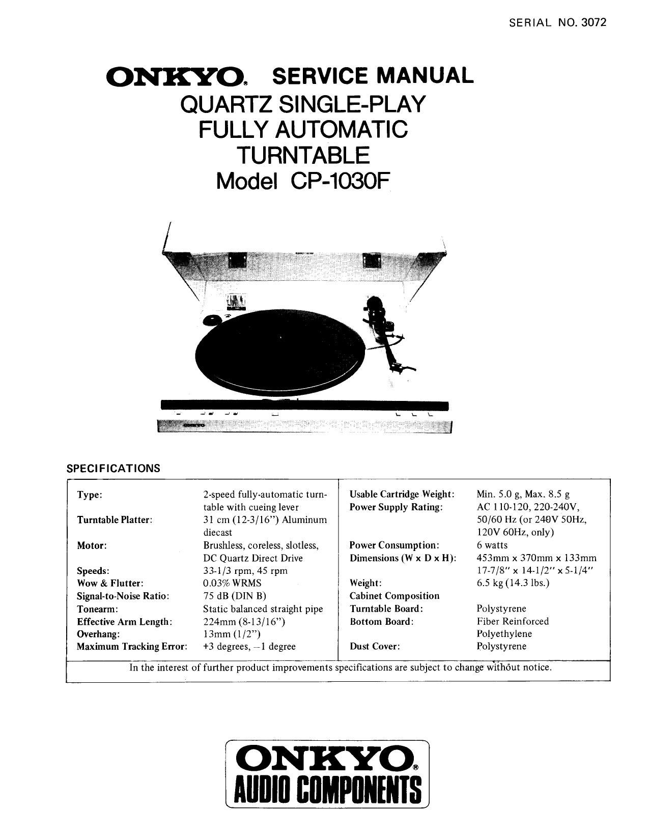
Onkyo CP 1030 F Service Manual

This is the 8 pages manual for Onkyo CP 1030 F Service Manual.
Read or download the pdf for free. If you want to contribute, please mail your pdfs to info@audioservicemanuals.com.

Page: 1 / 8
left right
Onkyo CP 1030 F Service Manual

Extracted text from Onkyo CP 1030 F Service Manual (Ocr-read)


Page 1

ONKYO: SERVICE MANUAL
QUARTZ SINGLE-PLAY
FULLY AUTOMATIC
TURNTABLE
Model CP-1030F

SPECIFICATIONS

SERIAL NO. 3072

Type :
Turntable Platter:
Motor :

Speeds:

Wow & Flutter:
Signal-to-Noise Ratio:
Tonearrn:

Effective Arm Length:
Overhang:

Maximum Tracking Error:

2-speed fully-automatic turn-
table with cueing lever

31 cm (12-3/16) Aluminum
diecast

Brushless, coreless, slotless,
DC Quartz Direct Drive
33-1/3 rpm, 45 rpm

003% WRMS

75 dB (DIN B)

Static balanced straight pipe
224mm (8-13/16)

13mm (1/2)

+3 degrees, 71 degree

Usable Cartridge Weight:

Power Supply Rating:

Power Consumption:

Dimensions (W x D x H):

Weight:

Cabinet Composition
Turntable Board:
Bottom Board:

Dust Cover:

Min. 5.0 g, Max. 85 g

AC 1 10-120, 220-240V,
50/60 Hz (or 240V 50Hz,
120V 60Hz, only)

6 watts

453mm x 370mm x 133mm
17-7/8" x 14-1/2" x 54/4
6.5 kg(l4.3 lbs.)

Polystyrene
Fiber Reinforced
Polyethylene
Polystyrene

In the interest of further product improvements specifications are subject to change without notice

ON KYO:
Alllllll lillMPflllllllS

Page 2

BLOCK DIAGRAM

rczcs
an'nge
rater

mm .m a l
Autoaetum
Pull in"

Gmrsmtch

maszzecm
rm Cons!


rim Canst

E
in

Service Technology (Part 1)
Note 1. Refer to the circuit diagram and block diagram.

2. L and H denote TTL positive logic, while the
figures in circles denote IC pin terminal numbers
and printed circuit board terminal numbers.

FF denotes flip-flop.

o

3.

Play operation

0 When ICla (2) is dropped to L" level, lCla (12) is
switched over to H" and IClb (6) is switched to H
to turn X203 on, the main gear drive motor is started.
When IC2b (4) is dropped to L level and IC2b (6)
switched to H level to turn X204, the record size
selector solenoid is actived.

When the main gear drive motor is started, the main gear
is rotated and SW7 gear switch is turned on.

When the main gear switch is turned on, lClc (11) is
switched over to L and lClc (8) is switched to H to
turn X207 on, the turntable platter drive motor is
started.

When the main gear is rotated, the tonearm is operated
and the tonearm switch is turned on.

When the lCSa (1) input of oscillator circuit is switched
H level, its circuit is operated, thereby the play
indicator repeat to turn on and off.

When the rotation of main gear is finished, the gear
switched restores R-F flip-flops to the initial condition
and the play indicator is turned on.

Reject Operation

0 WIienIClbO) is dropped to L level and IClb (6)
switched to H to turn X203 on, the main gear drive
motor is again started up.

When IC2c (10) is dropped to L level, IC2c (8) is
switched to H and 1C2b (6) to L to cut X204 off,
thereby inhibiting the record size selector solenoid.

Repeat Operation

0 When 1C4c (10) is dropped to L" level, 1C4c (8) is
switched to H and IC3b (5) kept at H. When lCZa
(l) is switched to H level, IC2a (12) is dropped to
L to turn the repeat indicator LED. on. When the
tonearm returns automatically at the end of the record,
IC206 (6) generates an H pulse ( J'LE) which is then
inverted by IC3d to become an L pulse. When this

1.:
x205
nanmui

x207
m

x701.
Driver


PLAY

Dlwer

Tn motor control PC a

Solenoid

3: Set input of flip-flop
R: Reset input of flip-flop
Ci, 6: Output of flip-flop
L: Low level (-12Vl

Notes:
REPEAI

K

pulse is applied to 1Cla (1), resulting in ICla (12) being
switched to H level. Thereby when [C3b (6) switched
L level, IC2b (6) switch to H to turn X204 on and
activate the record size selector solenoid.

To release the repeat mode, simply press the REJECT
key. In this case, IC2a(l3) is dropped to L level, IC2a
(12) switched to H and IC4c(8) to L, followed by
IC3b(5) being switched to L" and IC3b(6) to H
Then in conjunction with the reject operation described
above, the repeat mode is released by reject action. In
other words, the repeat mode is maintained only as long
as IC3b(5) is kept at H level.

Restoration of Initial Condition

When the main gear drive motor is started up for play or
reject operations, the main gear is also rotated. SW7
coupled to the main gear restores two R-S flip-flops initial
condition.

Auto-Return

When an eccentric pin of the lead arm coupled to the tone-
arm is inserted between D601 and 0601 , it serves as a shut-
off mechanism which turns the 0601 phototransistor off.
The difference in voltage is applied to a comparator via
IC206 (3), resulting in the generation of a positive pulse
which serves as the comparator output appearing at IC206
(6). This pulse is subjected to rectification and inversion at
the CR and IC3a, thereby forming a negative pulse which
is applied to IC1a(l). This is then followed by return or
repeat operation in the same way as described above.

Manual Play

When the tonearm is raised from the arm reset by hand,
the tone arm switch drops IClc(10) to L level, resulting
in IClc(8) being switched to H to turn X207 on, thereby
starting up the turntable motor by turn on of X207.