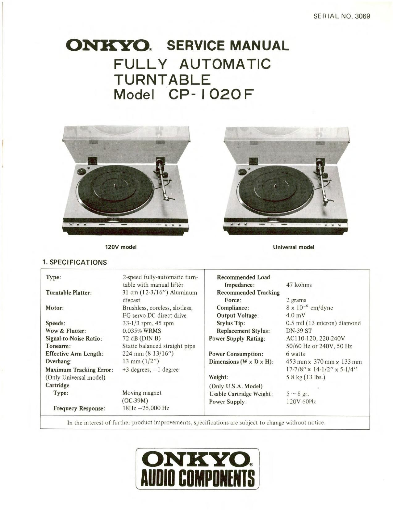
Onkyo CP 1020 F Service Manual

This is the 8 pages manual for Onkyo CP 1020 F Service Manual.
Read or download the pdf for free. If you want to contribute, please mail your pdfs to info@audioservicemanuals.com.

Page: 1 / 8
left right
Onkyo CP 1020 F Service Manual

Extracted text from Onkyo CP 1020 F Service Manual (Ocr-read)


Page 1

SERIAL N0. 3069

ONKYO, SERVICE MANUAL

FULLY AUTOMATIC

TURNTABLE
Model CP- l OZOF

120V model Universal model

1. SPECIFICATIONS

Type: 2-speed fully-automatic turn- Recommended Load
table with manual lifter Impedance: 47 kohms
Tumtable Platter: 31 cm (12-3/16) Aluminum Recommended Tracking
diecast Force: 2 grams
Motor: Brushless, coreless, slotless, Compliance: 8 x 10⁶ crn/dyne
FG servo DC direct drive Output Voltage: 40 mV
Speeds: 33-1/3 rpm, 45 rpm Stylus Tip: 05 mil (l3 micron) diamond
Wow & Flutter: 0.035% WRMS Replacement Stylus: DN-39 ST
Signal-to-Noise Ratio: 72 dB (DIN B) Power Supply Rating: AC1 10-120, 220-240V
Tonearm: Static balanced straight pipe 50/60 Hz or 240V, 50 Hz
Effective Arm Length: 224 mm (8-13/16") Power Consumption: 6 watts
Overhang: 13 mm (l/Z) Dimensions (W x D x H): 453 mm x 370 mm x 133 mm
Maximum Tracking Error: +3 degrees, 71 degree 17~7/8" x 14-1/2 x 5-1/4"
(Only Universal model) Weight: 5-8 kg (13 lbs.)
Cartridge (Only U.S.A. Model)
Type: Moving magnet Usable Cartridge Weight: 5 ~ 8 gr.
(0039M) Power Supply: 130V oOll/
Frequecy Response: 18Hz 725,000 Hz

In the interest of further product improvements. specifications are subject to change without notice

ON KYOQ
Alllllll flflMPllllllllS

Page 2

I l'-l02lll

2. BLOCK DIAGRAM

mm mm .c
mszricn :E' 1.;

Dim mm mm 1',

eicvmsx

em mun
m m:

«mu-MN
11:1 .m m.

Lead-In and Return Control Circuits
Note 1. Refer to the circuit diagram and block diagram.

2. L and "H'denote TTL positive logic, while the
figures in circles denote lC pin terminal numbers
and printed circuit board terminal numbers.

3. FF denotes flip-flop.

Play Operation
OWhen lC2b (3) is dropped to I." level, lC2b(6)
switched over to H and lC20(8) to L, resulting in
the turntable motor being started up by the cut off
action of X7.

0 When lClb(3) is dropped toL level and lClb(6)
switched to H" level to turn X4 on, the record size
selector solenoid is activated.

0 When lCla (l) is dropped to L level and lCla(12)
switched to H to turn X3 on, the tonearm drive motor
is started.

Reject Operation

0 When lCla(2) is dropped to L level and lCla(12)
switched to H" to turn X3 on, the tonearm drive motor
is again started up.

0 When lClc(10) is dropped to L level, lClc(8) is
switched to H and lClb(6) to L to cut X4 off,
thereby inhibiting the record size selector solenoid.

Repeat Operation

0 When lC4b(4) is dropped to L level, [C4b(6) is
switched to H" and [C3b(5) kept at H". When the
tonearm returns automatically at the end of the record,
IC4a(3) generates an L pulse ( U ) which is then
inverted by lC4c to become an H pulse. When this pulse
is applied to lC3b(6), another L pulse is generated,
resulting in lClb(6) being switched to H level to turn
X4 on and activate the record size selector solenoid.
To release the reject mode, simply press the REJECT
key. In this case, IC2a(2) is dropped to L level,
.IC2a(12) switched to H and lC4b(6) to ,L followed
by lC3b(5) being switched to L" and [C3b(6) to H
Then in conjunction with the reject operation described
above, the repeat mode is released by reject aciton. In
other Words, the repeat mode 15 maintained only as long
as IC3b(5)' 1s kept at H level.

Restoration of Initial Condition

When the tonearm drive motor is started up for play or
reject operations, the main gear is also rotated, SW8
coupled to the main gear restores all FFs to the initial
condition.

Auto-Return

When an eccentric pin of the lead arm coupled to the
tonearm is inserted between D101 and 010], it serves as a
shutoff mechanism which turns the 0101 photo transistor
off. The difference in voltage is applied to a cumaparator
via lC5(3), resulting in the generation of a positive pulse
which serves as the comarator output appearing at lC5(6).
This pulse is subjected to rectification and inversion at the
CR and lC4a, thereby forming a negative pulse which is
applied to lCla(l) and lC4c(l2) and (13). This is then
followed by return or repeat operation in the same way as
described above.

Manual Play

When the tonearm is raised from the arm rest by hand, the
SW7 arm switch drops lC2b(4) to L" level, resulting in
lC2b(6) being switched to H" and lCla(l) to L", thereby
starting up the turntable motor by cut off of X7.

Stopping the Turntable Motor
OWhen the tonearm is retumed manually to the arm rest
lC2c(ll) is switched instantaneously to L" level and
lC2c(8) to H", thereby turning X7 on to bring the
turntable motor to a stop.

0 When the main gear starts to rotate during reject or auto-
retum mode, the SW8 gear switch is set to position (21)
during rotation, and to position (22) end the end of one
revolution. As soon as this single revolution is come
pleted, the base of X5 is switched to L" level, resulting
in a cut off action, and IC4d(lO) being switched to H.
The SW7 arm switch is at position (24) (on the arm rest)
at this time, and IC4d(9) is at H level. At the instant
that IC4d( 10) is switched to H", IC4d(8) is switched to
L IC2c(l l) to ",L and lC2c(8) to ",H resultingin
X7 being turned on to stop the turntable motor,

Power On Reset

When the power switch is turned on, the FFs at X8, X9 and

X10 are rest to their prescribed initial state. (X9 is cut off

immediately, while X8 and X10 are cut off according to

their respective time constants).