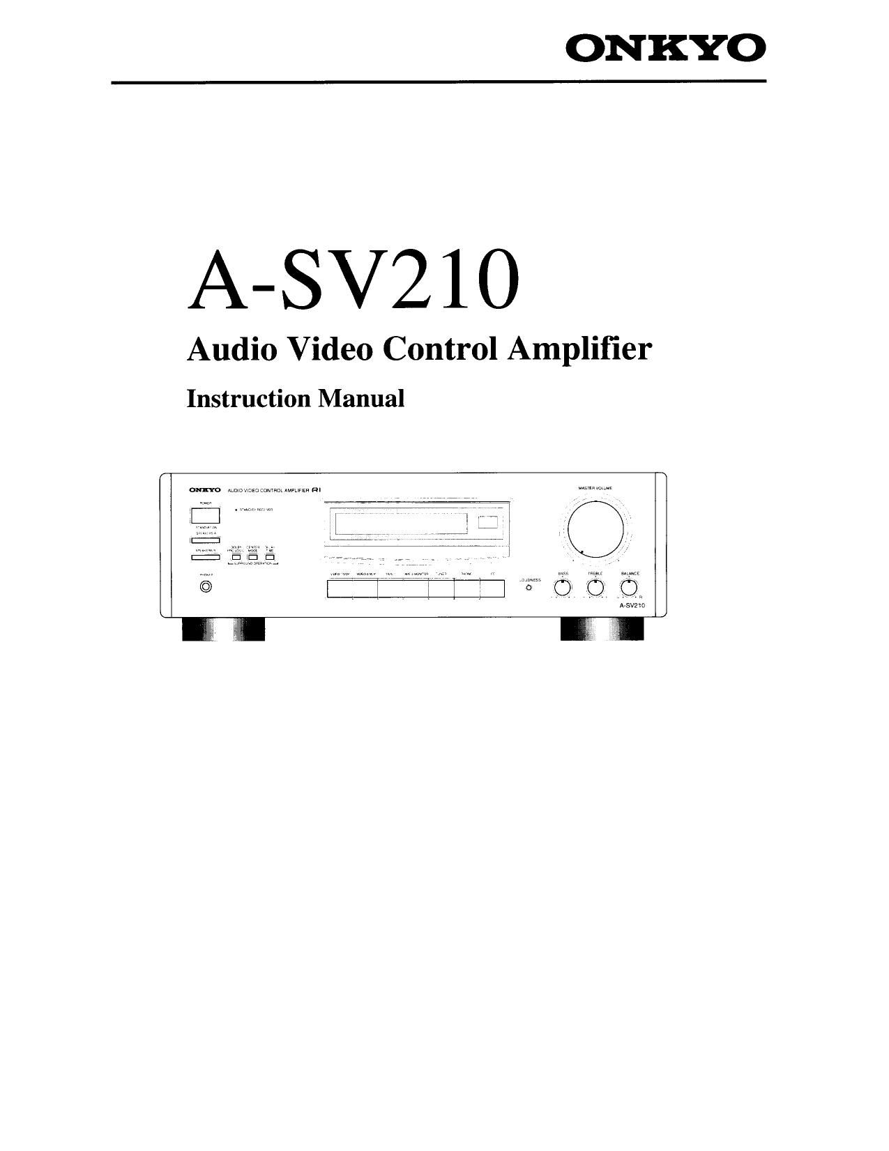
Onkyo ASV 210 Owners Manual

This is the 20 pages manual for Onkyo ASV 210 Owners Manual.
Read or download the pdf for free. If you want to contribute, please mail your pdfs to info@audioservicemanuals.com.

Page: 1 / 20
left right
Onkyo ASV 210 Owners Manual

Extracted text from Onkyo ASV 210 Owners Manual (Ocr-read)


Page 1

ONKYO

A-SV210

Audio Video Control Amplifier

Instruction Manual

l: . ,W m
:1
©

Page 2

Thank you for your purchase of the Onkyo A-

SV'l 10 Amplifier.

Please read this manual thoroughly before making con-
nections.

Following the instructions in this manual will enable you
to obtain Optimum performance and listening enjoyment
from your new A-SV210.

Please retain this manual for future reference.

Features

I Powerful A/V Amplifier with Discrete Outputs

Plenty of pristine power drives your home theater system to
perfection. In surround mode: 60 watts per channel (8 ohms) to
your front L/R and center speakers, plus 15 watts per channel
to your IJR surround speakers. Stereo mode: 100 watts per
channel (8 ohms). Discrete output stage circuitry for all chan-
nels contributes to your A-SV210s ability to drive low-imped-
ance speakers safely and without degraded performance.

I Dolby Pro Logic Surround Sound
Now you can experience the highest standards of video sound
performance. Along with left and right front speakers and rear
surround speakers, the Dolby Pro Logic decoder adds a center
channel speaker dedicated to dialogue. So main voices stay
right where they belong i with the picture.

I Input Selector for 2 Video and 5 Audio Sources
You can connect two VCRs or a VCR and laserdisc player to
your A-SV210 to easily make copies or edit tapes from one
VCR to another, or record from laserdisc or TV to your VCR.
And five audio inputs assure you of enough inputs for your
present and future audio needs.

I Mono Out (Subwoofer Output)

A line»leve| subwoofer output lets you connect an active sub-
woofer. so you can enjoy a new dimension in low-bass excitement.

I RI (Remote Interactive) Compatible Remote Control
After making the appropriate connections, you can control with
one remote virtually all of your A-SVZIO's functions, as well
as the major functions of other Onkyo components bearing the
RI symbol.

I Adjustable digital delay

I Auto input balance

I Loudness control

I Motor-driven volume control

I Muting and sleep timer (by remote)
I Headphone jack

I Battery-free memory backup

I Anti-vibration feet and chassis

I Solid aluminum front panel

o For models having a power cord with a polarized plug.
CAUTION: To PREVENT ELECTRIC SHOCK. MATCH
WIDE BLADE OF PLUG T0 WIDE SLOT. FULLY INSERT.

o Sur les modeles dont la fiche est polarisée.
ATTENTION: POUR EVITER LES CHOCS ELEC»
TRIQUES, INTRODUIRE LA LAME LA PLUS LARGE DE LA
FICHE DANS LA BORNE CORRESPONDANTE DE LA
PRISE ET POUSSER JUSQAU FOND.

Supplied accessories

1 Remote control

2 Batteries (size AA, R6, or UM-3)
| Remote control cable

For USA and Canada

0 Manufactured under license from Dolby Laboratories
Licensing Corporation.
Additionally licensed under Canadian patent number
1,037,877. Dolby, Pro Logic, and the doubleeD symbol
are trademarks of Dolby Laboratories Licensing Corpora-
tton.

F or Other area

a Manufactured under license from Dolby Laboratories
Licensing Corporation.
DOLBY and the double-D symbol are trademarks of Dolby
Laboratories Licensing Corporation.

WARNING

TO REDUCE THE RISK OF FIRE OR ELECTRIC SHOCK,
DO NOT EXPOSE THIs APPLIANCE TO RAIN 0R MOIS-
TURE.

CAUTION:

TO REDUCE THE RISK OF ELECTRIC SHOCK, DO NOT
REMOVE COVER (OR BACK), N0 USER-SERVICEABLE
PARTS INSIDE. REFER SERVICING T0 QUALIFIED SER-
VICE PERSONNE

CAUTION

RISK OF ELECTRIC SHOCK
DO NOT OPEN

A
A

&

. The lightning flash with arrowhead symbol.
within an equilateral triangle, is intended tn alert
the user to the presence of uninsulatcd danger-
ous voltage" within the products enclosure that
may be of sufficient magnitude to constitute a
risk of electric shock to persons.

I The exclamation point within an equilateral trian-
gle is intended to alert the user to the presence of
important operating and maintenance (servicing)
instmctions in the literature accompanying the
appliance.

Page 8

Making system connections

Connect the VIDEO output of the VCR to
the rear panel (VIDEO) VIDEO-2 IN
jack and the VIDEO input of the VCR to
the rear panel (VIDEO) VIDEO-2 OUT"
jack. Then connect the AUDIO output of
the VCR to the (AUDIO) VIDEO-2 L and
R IN"jackst Finally, connect the AUDIO
input of the VCR to the (AUDIO) VIDEO-
2 L and R OUT" jackst
0 When using a playback»only VCR, you
only need to make the output connec-
tions.
0 For more details refer to the VCR

instruction manualt

it
BEE l. Connect the TV VIDEO input to this
° 0° 00° unit MONITOR OUT". jack. There is
00000000- EEEE _ t .
oooooooog no need to pertorm an audio connection
since sound will be sent directly from
this unit lo the speaker systems

' 2. This unit can be used with only a monL
VlDEO IN tor TV equipped with a video input
jack.
3. Interference may be caused between the
TV and this unit.
If this interference occurs place this unit
and the TV as for apart as possible.

The SWITCHED outlet is switched on and

off by the power button: on the from panel
and remote control.

gggggggggc EBEB Be careful that other components con-
nected to this unit do not exceed the capace
ity that is printed on the rear panel above
Capacity is total the AC Oullelst

120 watts

Page 12

Recording a source

1~3
Q |@|
[3 one a

_Tape deck
(TAPE-1, TAPE-2)

2

VlDEOi/VDP VIDEO-2N0}? VAPE-l rAPEzMONrrOR TUNER

1-3
E

:F
Doom: oooO Dooog

Tape deck (TAPE-1) Tape deck (TAPE-2)

we: momma

12

Plea. read the instmction manuals con

cerning the operation of each unit.

1. Insert a blank tape into the tape deck.

2. Press the button of the source from
which you want to record.

0 When VIDEOel/VDP or V1DE0A2/
VCR is selected, it will (naturally) only
record the audio

0 When TUNER is selected, set the tuner
to the station you want to record from.

0 When TAPEel is selected. it will record
to the TAPE-2 REC jacks

0 When either VIDEOJNDP, VIDEO,
2/VCR, TUNER PHONO or CD is
selected, you are able to record to both
the TAPE-1 and TAPE-2 RECjacksr

3. Put the tape deck in the recording
mode. Begin playing the source.

Set the proper recording level usmg the
controls on the tape deck used for record-
ing Also, during recording and dubbing
operations. if any controls (bass. treble
etc.) on this unit are changed during
recording and dubbing operations the tone
effects will not change.

1. Load the original tape in deck 1 and
the blank tape in deck 2.

2. Press the TAPE-1 button.

3. Put tape deck 1 in the playback mode
and tape deck 2 in recording mode.

The source signal can be monitored
through the speakers or headphones
when TAPE-2 MONITOR is turned off.
If tape deck 2 has three heads. the just-
recorded signal can be monitored (when
the TAPE-2 MONITOR is Iumed on).
Refer to the tape deck instruction manual
for more details.