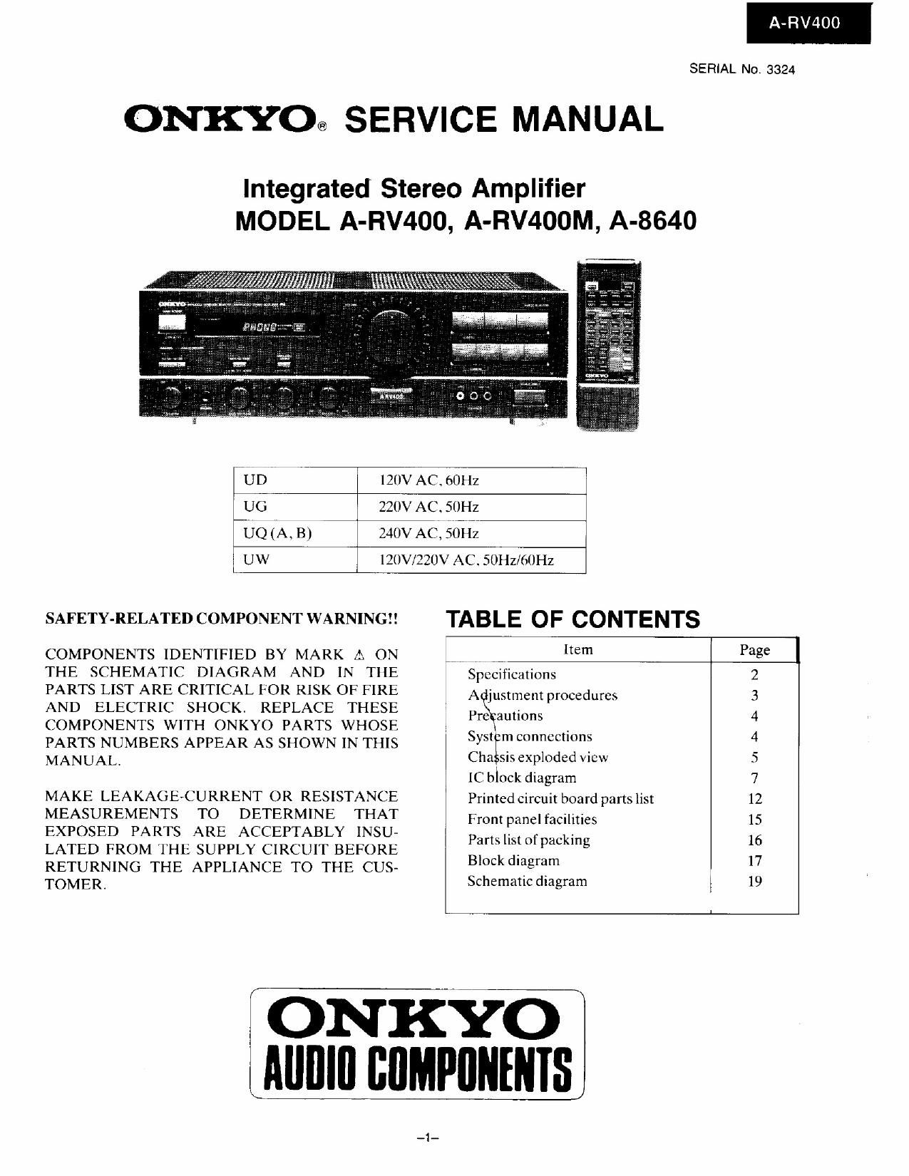
Onkyo ARV 400 M Service Manual

This is the 17 pages manual for Onkyo ARV 400 M Service Manual.
Read or download the pdf for free. If you want to contribute, please mail your pdfs to info@audioservicemanuals.com.

Page: 1 / 17
left right
Onkyo ARV 400 M Service Manual

Extracted text from Onkyo ARV 400 M Service Manual (Ocr-read)


Page 1

A-RV400

SERIAL No. 3324

ONKYO@ SERVICE MANUAL

Integrated Stereo Amplifier
MODEL A-RV400, A-RV400M, A-8640

7' UD7 I 120v AC. (IOHZ
U6 7 220v AC. 50Hz
-UQ(A. B) V 240v ACI.S6HZ
I UW 7 . l?(]V/22(JV ACSOIIz/mHz

SAFETY-RELATEDCOMPONENTWARNING!! TABLE OF CONTENTS

COMPONENTS IDENTIFIED BY MARK 12. ON w "em Page
THE SCHEMATIC DIAGRAM AND IN THE Specifications 2
PARTS LIST ARE CRITICAL FOR RISK OF FIRE Adjuslmem procedures 3
AND ELECTRIC SHOCK. REPLACE THESE Pagaunom 4
COMPONENTS WITH ONKYO PARTS WHOSE : , . ,
PARTS NUMBERS APPEAR AS SHOWN IN THIS 535?" "10 4
MANUAL. Cha Sis exploded View 5
[C block diagram 7
MAKE LEAKAGE-CURRENT 0R RESISTANCE Prinlcdcircuit board partslist 12
MEASUREMENTS TO DETERMINE THAT Fronwanelfadmics 15
EXPOSED PARTS ARE ACCEPTABLY INSU- Pamlismf ackin 16
LATED FROM THE SUPPLY CIRCUIT BEFORE M, F g
RETURNING THE APPLIANCE To THE CUS- 3 gm" '7
TOMERI Schematicdiagram I 19

; ONKYO
i Alllllll BflMPflNHflS

Page 7

REF. NO.
U010

UUII

UIJII

U012

lC BLOCK DIAGRAM

LC6527C (Remoto controlle decoder)

PART NO.
IAI4357071A

DESCRIPTION

NAETC-3570- 1A, BUS
TERMINAL PC BOARD ASSY
[GllwllAllBl

lAI43571-l NAETC-3S7l-1.VIDEO
TERMINAL PC BOARD ASSY
[DI

lAl4357l-IA NAETC-3571-IA.VIDEO
TERMINAL PC BOARD ASS'Y
[GllWllAllBl

lAl43572vl NADISA3572-I.VOLUME

INDICATOR PC BOARD
ASS'Y

A-RV400

NOTE: [D]: ONLY 1qu MODEL
[G]: ONLY 22w MODEL
[W]: ONLY 120V/220V MODEL
[A]: ONLY AUSTRALIAN MODEL
[B]: ONLY BRITISH MODEL

NOTE: THE COMPONENTS IDENTIFIED BY MARK A
ARE CRITICAL FOR RISK OF FIRE AND ELEC-
TRIC SHOCK. REPLACE ONLY WITH PARTS
NUMBER SPECIFIED.

m u (-- Ill sins

vcn m -> 5V5 our

Pin No. Pin mime Symbol Function
1 OSCI OSCI Ceramic oscillator connectorterminal. 4 MHZ. 1/3 division
2 TEST TEST Test terminal. Connected to V.
3 V V53 Ground terminal
4 RES RES Reset terminal.
5 PA() CUSTOM Decoded input terminal with switchable custom codes and operations.
Custom input Custom code Operation
L D26D System (export)
H D225 Tuner
1 This terminal is read when power is turned on and the above initial settings
are carried out.
6 PA I STAND BY Standby condition sensor terminal. Only the POWER code is decoded when
STAND BY input is "".L
1 7 PAZ EM IN Remote control signal input terminal. Active: ".L The photo-sensor output
a is connected to this terminal.
f 8 PA3 SYS IN System code input terminal. Active: "".H Output system codes are
monitored at this terminal.
9 VDD VDD Power supply (+5V) terminal.
10 PCO SYS OUT System code output terminal. Active: L. This terminal output the
appropriate system code in response to input from the remote control.
11 PCI PH SENS PHONO sensor input terminal. Active: L". This terminal is valid durtng system.
The remote control K64 code is decoded only when this terminal
is L".
12 PCZ RECEIVE RECEIVE display output terminal. Active: 'L. L" when remote control
codes for decoding are being input.
13 PC3 VOL IND VOLUME indicator output terminal. Active: TL Normally "L. Outputs
waveform which is H for 250 ms then "L" for 250 ms during VOLUME
UP or VOLUME DOWN output.
14 PDO VOL DOWN VOLUME DOWN control output terminal. Active: "H". Output is "H"
when remote control K4 code is input.
15 PDI VOL UP VOLUME UP control output terminal. Active: "H Output is "H" when
remote control K3 code is input.
16 PDZ PLAYER PLAYER control output terminal. Active: H". This terminal is valid during
system. Output is " for 200 ms if remote control K64 code is input when
PH SENS input is ".L
17 PD} POWER POWER control output terminal. Active: "H Reverses output whenever
remote control K5 code is input.
18 OSCZ/PHO OSCZ Ceramic osciIIator connectorterminal. 4MI-Iz 1/3 division.

-7-