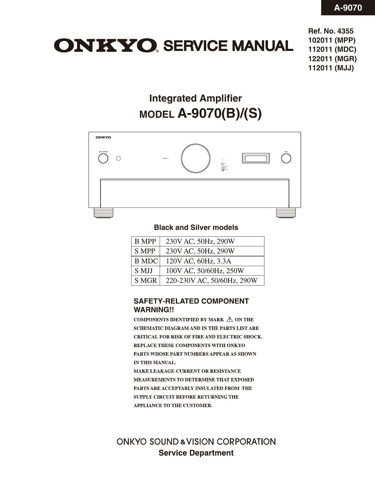
Onkyo A 9070 Service Manual

This is the 81 pages manual for Onkyo A 9070 Service Manual.
Read or download the pdf for free. If you want to contribute, please mail your pdfs to info@audioservicemanuals.com.

Page: 1 / 81
left right
Onkyo A 9070 Service Manual

Extracted text from Onkyo A 9070 Service Manual (Ocr-read)


Page 1

ONKYO, SERVICE MANUAL

Integrated Amplifier
MODEL A-9070(B)/(S)

© C)

@

ONKYO SOUND &V|SION CORPORATION

Black and Silver models

B MPP 230V AC, SOHZ, 290W

S MPP 230V AC, SOHZ, 290W

B MDC 120V AC, 60Hz, 3.3A

S MJJ 100V AC, 50/60Hz, 250W

S MGR 220-230V AC, 50/60Hz, 290W

SAFETY-RELATED COMPONENT
WARNING! !

COMPONENTS IDENTIFIED BY MARK A ON THE
SCHEMATIC DIAGRAM AND IN THE PARTS LIST ARE

CRITICAL FOR RISK OF FIRE AND ELECTRIC SHOCK.

REPLACE THESE COMPONENTS WITH ONKYO
PARTS WHOSE PART NUMBERS APPEAR AS SHOWN
IN THIS MANUAL.

MAKE LEAKAGE-CURRENT OR RESISTANCE
MEASUREMENTS TO DETERMINE THAT EXPOSED
PARTS ARE ACCEPTABLY INSULATED FROM THE
SUPPLY CIRCUIT BEFORE RETURNING THE
APPLIANCE TO THE CUSTOMER.

Service Department

A-9070

Ref. No. 4355
102011 (MPP)
112011 (MDC)
122011 (MGR)
112011 (MJJ)

Page 2

A 00 [9070

Service Procedures

1.0peration check
1) Speaker relays
The relay shall be ON about 5 seconds after POWER is ON and shall be OFF immediately after POWER is OFF.
2) Voltage-detection protectors
The speaker relay is OFF immediately after DC. 3V is put at MAIN IN INPUT terminal to check SP:B(L/R).
The same as above when D.C. -3v is put at each place. TEST24-02.
3) Current-detection protectors
a) The relay shall be ON when 3 ohm load is connected to each channel under the conditions of peak-to-zero 35V output
for L,Rchannels and no load by using the INTEGRA ampifier series designated circuit with ZOOHZ square wave.Use
TESTz2-17 MAIN IN mode input MAIN IN.
b) The relay shall be OFF when 15 ohm load is connected to each channel under the conditions of peak-to-Zero 35V
output for L,R channels and no load by using the the INTEGRA ampifier series designated circuit with 200Hz square

wave. White LED

If a relay goes out, Disconnect input signal immediately. Model
Don't continue to do this check 3 seconds or more.

4) FL tube test (All lighting check) "9000" A9070
Please confirm the all FL display lights by TEST MODE 'TEST-1-00'. Normal X X

5) Buttons Dimmer x x
Please confirm by TEST MODE 'TEST-1-01'.

6) DIMMER F'- OFF 0 x

Please push DIMMER button of Remote controller and confirm the brightness of FL display changes and the white LED
lights(A-9000R only).
7) Firmware version.
Set the test mode "0-01. Please check the Firmware version.
8) Adjustment and Confirmation of Destination

a) Please confirm the R1293 on the BADG-O998. Destination
When destination is MJJ or MDC or MGR,lt is nothing on the PWB. MPP etc
When destination is MPP, It exist on the PWB. R1293 o x

b) Set the test mode "0-02".
Please check Model Number. Destination

c) Set the test mode "0-03".
Please check Destination. MPP etc
Please check the display of FL refer to right table. Display MPP NMPP

9) Auto Standby (ASb) detection circuit

a) Set the test mode "4-00".

b) Confirm that the character of "ASb" is not displayed in FL display under the condition of no signal.

c) Confirm that the character of "ASb is displayed in FL display, when "-20dBV,-14dBV, 1kHz" signal is input to Linet

Terminal.

2. To initialize the unit.
Press ON/STANDBY button in the TEST MODE, then the FL displays "CLEAR", and turn to STAND-BY mode.
Remove AC cord from INLET,

3. Initial setting
Mechanical Power Switch - ON
Phono MM/MC Switch - MC
Direct SW - OFF

TEST MODE
1)Set volume OdB and push ON/STANDBY button while pushing down SET UP button to display "TEST-,".
2) Next, if the following keys are pushed. it becomes a each TEST MODE.

TEST MODE
0-00 1-00 2-00 3-00 4-00
NO PUSHED TREBLE - TREBLE + BALANCE L BALANCE R

3) In the test mode, The TEST MODE number goes up if the selector knob is turned to the right.
The TEST MODE number goes down if the selector knob is turned to the left.