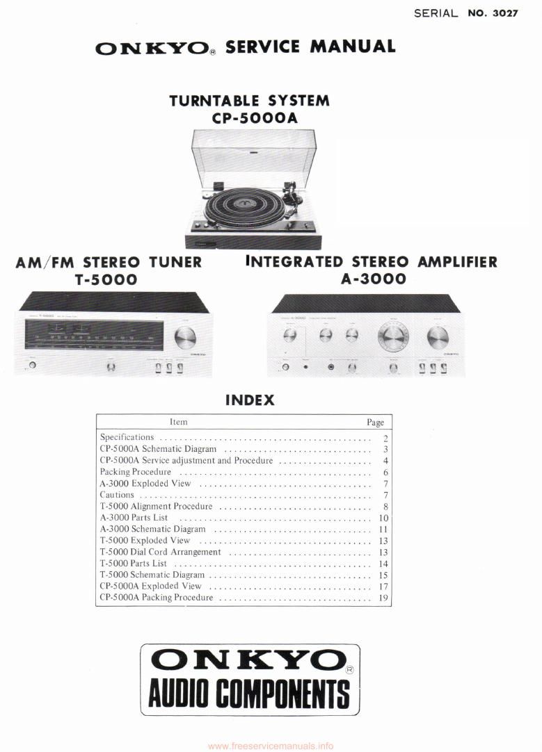
Onkyo A 3000 Service Manual

This is the 16 pages manual for Onkyo A 3000 Service Manual.
Read or download the pdf for free. If you want to contribute, please mail your pdfs to info@audioservicemanuals.com.

Page: 1 / 16
left right
Onkyo A 3000 Service Manual

Extracted text from Onkyo A 3000 Service Manual (Ocr-read)


Page 1

SERIAL NO. 3027

O N KYOa, SERVICE MANUAL

TURNTABLE SYSTEM
CP-SOOOAV

l

_
AM/FM STEREO TUNER INTEGRATED STEREO AMPLIFIER
T-5ooo A-3000

_ -
7 II- 93 u 4-? 4 "1353 $$

lmn Page
Specitluuuons .......................................... 3
(P~5000.~\ Schcmulic Drugrum .............................. 3
(P-SOOOA Scrvmc adjustment and Procedure ................... 4
Packing Procedure ...................................... 6
A-3000 Exploded View ................................... 7
Cautions ............................................ 7
1-5000 Alrgnment Procedure ............................... 8
A-3000 Parts List .r .. .................................. 10
A3000 Schematic Diagram ................................ ll
T-SOOO Exploded View .................................. l3
T-SOOO Dial Cord Arrangement ............................. 13
T5000 Parts List ....................................... l4
T-SOOO Schematic Diagram ................................. 15
CP-SOOOA Exploded View ................................. l7
CI»5000A Packing Procedure ............................... l0

o N KYO?
Alllllll BIIMPIINENISJ

Page 5

Replacement of Motor

As for the screws for mounting motor, there are two kinds used, i.e., one chrome plated panhead screw (2.6 x 4) and two
unichrome plated panhead screw (2.6 x 3) for ground co-fastening part. If the 4m/m size screw is applied to the portion
of the 3m/m size screw, the motor insulation rubber is damaged to provide unstable motion of motor. Be careful not to
mistake. Spring washers are provided for fastening purpose. Never fail to use them.

Replacement of Belt

1)

2)

3)

In order to give an improved stability of the tension of the belt from the Viewpoint of the motor construction, a
one-side shaped belt is used. For replacement, please use the regular one SN242129B. The SN of the conventional
both side out belt is 242129. With regard to the one-side polished belt, the use in a manner that the polished side is in
contact with the pulley and the turntable is the correct method, but the reverse manner may also be practically
acceptable, where the S/N ratio and the revolution vary to a Very slight degree. The polished surface is the side where
the surface is uniform and mat. The opposite side is slightly lustrous and uneven.

The pulley is a single step without any belt guide.

Apply the belt to the turntable to the side near the lower end of the drum. Should the belt be set to the upper side,
it would slip upward to the flange of the pulley at the time of the application to the pulley, with the result that the
correct revolution may not be obtained or the belt may go out of the pulley.

Since the shaft of the motor is extremely fine at 21), be careful that any collision of turntable, etc. during service
may cause a bend to the shaft or an irregular revolution in consequence of the deviation of the position of the bear-
ing holder, etc.

Fitting of Neon Lamp
Fit the neon lamp in a manner to set the electrode of the neon lamp nearly to the center of the claw of the lamp holder.
If the neon lamp is not correctly fitted, the lamp house may include a dark area for lighting.

Others

1)

2)
3)

4)

Since the stopper of TT shaft is a molded product, do not use the one once disconnected but replace with a new one
(because the continued use provides a cause for the leakage of oil and the coming off of shaft).

For lubrication of TT shaft, use the oil of ANDEROL #465 or #102.

For lubrication of motor bearing, the oil of IAUNA #40 is used. Use of other oil may cause irregular rotation and
unstable revolution.

For disconnecting the PC plate, extract after sufficiently constricting the stopper for the mold.

Be careful not to exert unreasonable power for disconnecting the PC plate. or the PC plate will cause breakage.