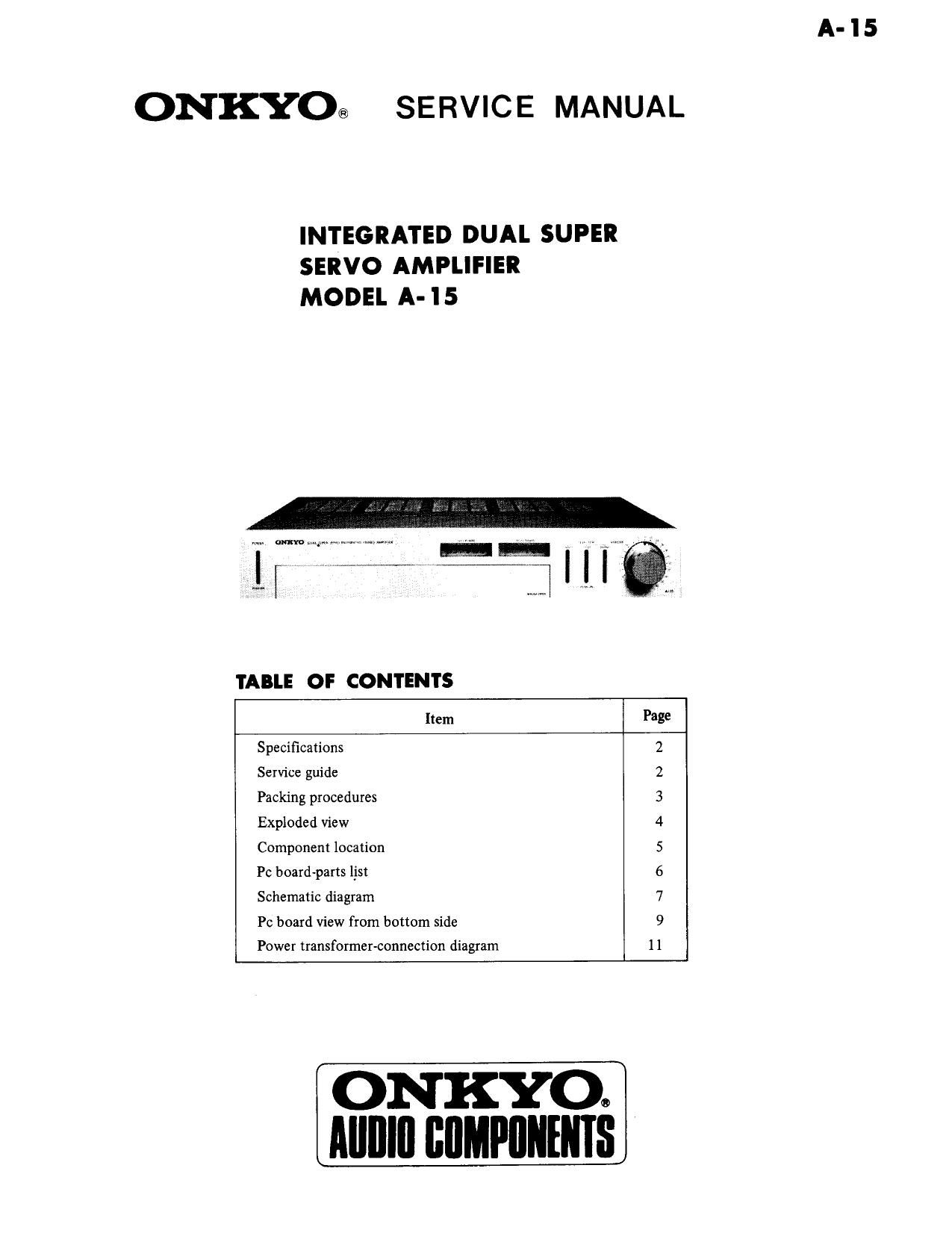
Onkyo A 15 Service Manual

This is the 9 pages manual for Onkyo A 15 Service Manual.
Read or download the pdf for free. If you want to contribute, please mail your pdfs to info@audioservicemanuals.com.

Page: 1 / 9
left right
Onkyo A 15 Service Manual

Extracted text from Onkyo A 15 Service Manual (Ocr-read)


Page 1

A-IS

ONKYO® SERVICE MANUAL

INTEGRATED DUAL SUPER
SERVO AMPLIFIER
MODEL A- 15

TABLE OF CONTENTS

g

Item

Specifications
Service guide
Packing procedures
Exploded View
Component location
Pc board-parts list

Schematic diagram

\D\IO\U<>WNI\J

Pc board View from bottom side

H
._-

Power transformer-connection diagram

ONKYOO
AIIIIIII BflMPIIIIEIIIS

Page 2

SPECIFICATIONS

Continuous Power
Output:

30 watts per channel min. RMS, at
8 ohms both channels driven, from

20Hz to 20kHz, with no more
than 0.08% THD

Total Harmonic 0.08% at rated power

Distortion:
IM Distortion: 0.08% at rated power
Damping Factor: 40 at 8 ohms.
Frequency Response: 15 - 30,000Hz i1 dB
Sensitivity and Phone : 2.5 mV/50 kohms
Impedance: Tuner : 150 mV/50 kohms

Tape Play : 150 mV/50 kohms
Tape Rec. : 150 mV/3.5 kohms
(Phone)
Phone Overload:
Bass Control:
Treble Control:

:8 dB at100Hz
18 dB at 10,000 Hz

SERVICE GUIDE
1. Replacing the fuse

For continued protection against fire hazard, replace only

with same type and same rating fuse.

1. AC fuse
Remove the top cover.
Circuit No. Parts No. Description
U.S.A. model
F901 252049 4A(ST-6)
1201/ model (axe-pt USA. model)
F901 252014 4A-T
220v model
F901 252074 2A»SE-EAK
F911, F912 252078 5A~SE-EAK
120/220v model
F901 252014 4A-T
F902 252074 2A-SE-EAK
2. Speaker protection fuse
Remove the top cover.
F501 , F601 25 2094 4A-T-A

2. Protective circuit

This model has a built-in thermal switch to protect the
power IC. The thermal switch is not activated under normal
operating conditions.

However, if there is an abnormal rise in the inside tem-
perature, the thermal switch cuts off the outputs,

(The pilot lamp will not turn off.)

When this occurs, wait for a while until the temperature is
cooled down after remove the abnormal conditions.
(Abnormal condition means operation with a load below
4 ohms, or under poor conditions with high power such as a
place with in sufficient air circulation.)

150 mV HMS at 1kHz, 0.08% THD

Signal to Noise Phono : 75 dB
Ratio: (IHF A-202, 5 mV input, 1 watt
output)
Tuner & Tape : 80 dB
(IHF A-202, 0.5 V input, 1 watt
output)
Loudness: 16 dB at 70 Hz
:5 dB at 10 kHz
General
Power Supply: AC 220V, 50Hz.
AC 120V, 60Hz
AC 120V/220V, 50Hz/60Hz
Semiconductors: 4 ICs, 2 transistors, 16 diodes,

Dimensions: 418(W) x 75(H) x 230(D) mm
16-1/2" x 3"x11"

6.4 kg, 14.1 lbs

Specifications and features are subject to change without
notice.

Weight:

LLf

:1 12::

3. Voltage Selector (Rear Panel)

Some models are equipped with a voltage selector to con-
form with local power supplies.

Be sure to set this switch to match the voltage of the power
supply in your area before turning the power switch on.
Voltage is changed by sliding the groove in the switch with
a screwdriver to the right or left. Confirm that the switch
has been moved all the way to the right or left before turn-
ing the power switch on.

If there is no voltage selector switch on the unit you have
purchased, it can only be used in areas where the power
supply voltage is the same as that of the unit.