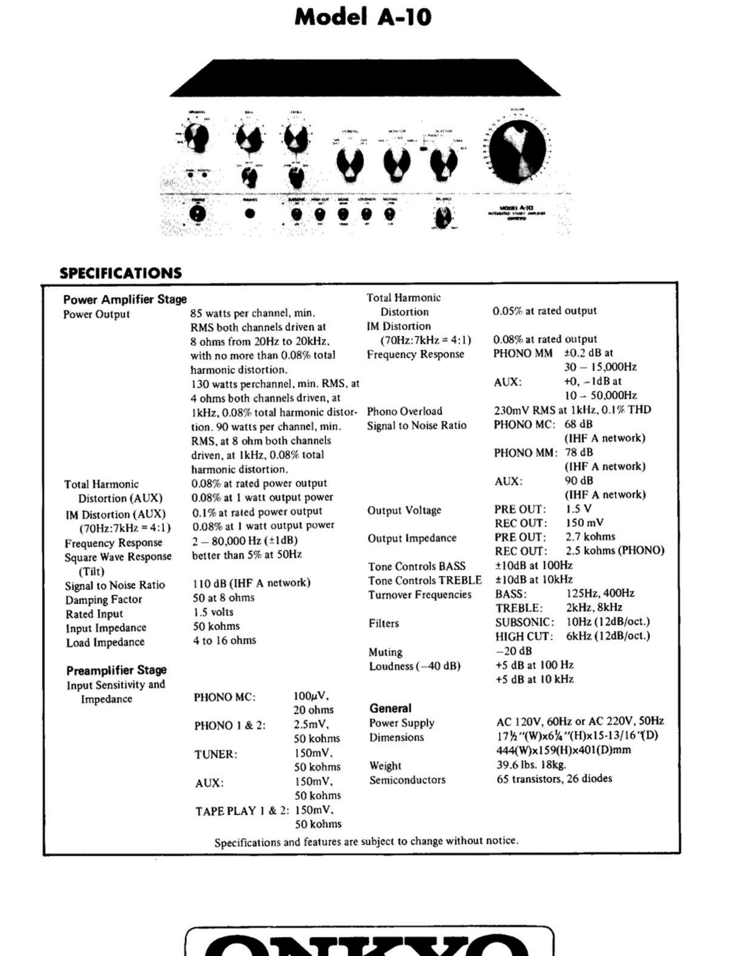
Onkyo A 10 Service Manual

This is the 11 pages manual for Onkyo A 10 Service Manual.
Read or download the pdf for free. If you want to contribute, please mail your pdfs to info@audioservicemanuals.com.

Page: 1 / 11
left right
Onkyo A 10 Service Manual

Extracted text from Onkyo A 10 Service Manual (Ocr-read)


Page 2

CIRCUIT DESCRIPTION
1. SPEAKER PROTECTION CIRCUIT

The speaker protection circuit is operated:

1) When the B circuit is unstable when the power is turned ON (approximately 5 seconds).

2) When the speaker terminals are shorted and abnormal current has flowed in the power amplifier thru this low im-
pedance.

3) When the center voltage has increased because of trouble at the differential amplifier. etc.

4) When the temperature of the heat sink has risen.

ROI 0 I 7 Q703 0704, Q705 Q706
CURRENT PROTECTION SCHMITT HOLD
from DETECTOR ' CIRCUIT TRIGGER CIRCUIT
collect SWITCH I
of Power
Amp. Current Q7 07
detection
. PROTECTION
level SPEAKER INDICATOR
0702 RELAY SWITCH
NEGATIVE Rum C5
VOLTAGE
PROTECTION
__+ DETECTOR INDICATOR
from 0701
Power POSITIVE
Amp. VOLTAGE
DETECTOR Protection Circuit Block Diagram

When Q703 is turned on by voltage detection or current detection. 0704 is turned ON by the voltage drop across R709.
0704, Q705 constitute a digitalized. fast response Schmitt trigger circuit. When 0704 is turned ON. 0705 is turned OFF.
0705 is a relay drive transistor. When it is turned OFF. the relay is also turned OFF.

When the power switch is turned ON. charging current flows thru the loop R710 - C703 -* R708-3'R709 and 0704 is
turned ON by the voltage drop across R709. Consequently. Q705 and the relay are turned OFF until the charging
current drops below a certain value. When the power switch is turned OFF. the B voltage falls and C703 is quickly dis-
charged thru the loop C703 -+ R710 » D701. During normal operation. C703 is charged to almost the B voltage. But since
the saturation resistance of 0703 is sufficiently low. when Q703 is turned ON. C704 is quickly discharged thru the loop
C703 -> R710 -> Q703 and the relay is also turned OFF. The relay is not turned ON again thereafter until C703is charged,
even if the set should return to normal and Q703 is turned OFF.

HOLD CIRCUIT

The reference voltage-is produced by R716, R717, 0706 is operated as a comparator. When Q705 has been turned OFF,
the collector voltage of Q705 rises and C706 is charged. Therefore. when C706 is charged to above a certain voltage
relative to the reference voltage at the junction of R716 and R717, Q706 is turned ON. 0703 is turned ON thru R728 and
the circuit is held.

CURRENT DETECTOR

017 is turned ON by the voltage detected from the collector cirsuit of the power amplifier. C24 prevents erroneous
operation. R61 sets the current detection level and tliermister R66 controls changes in the current detection level caused
by tempeature rise.

When the impedance is low at a certain frequency of the speaker. the protection circuit may be unexpectedly actuated each
time a large audio signal of that frequency has entered. However. when this occurs the relay is opened and the power ampli-
fier current returns to normal. The power amplifier current is also automatically returned to normal in a like manner when

the load has been inadvertently shorted momentarily.

When connected with the load shorted, the relay is repeatedly turned ON and OFF in load short -> relay OFF (no load) -+
automatic reset (load short current detection) -> relay OFF order. Since the OFF time is sufficiently longer than the relay
ON time in this case. the voltage across C705 gradually increases until a voltage sufficient to turn Q706 is reached. at which
time the relay is held OFF. thus protecting the power transistor against damage by a continuous overcurrent.