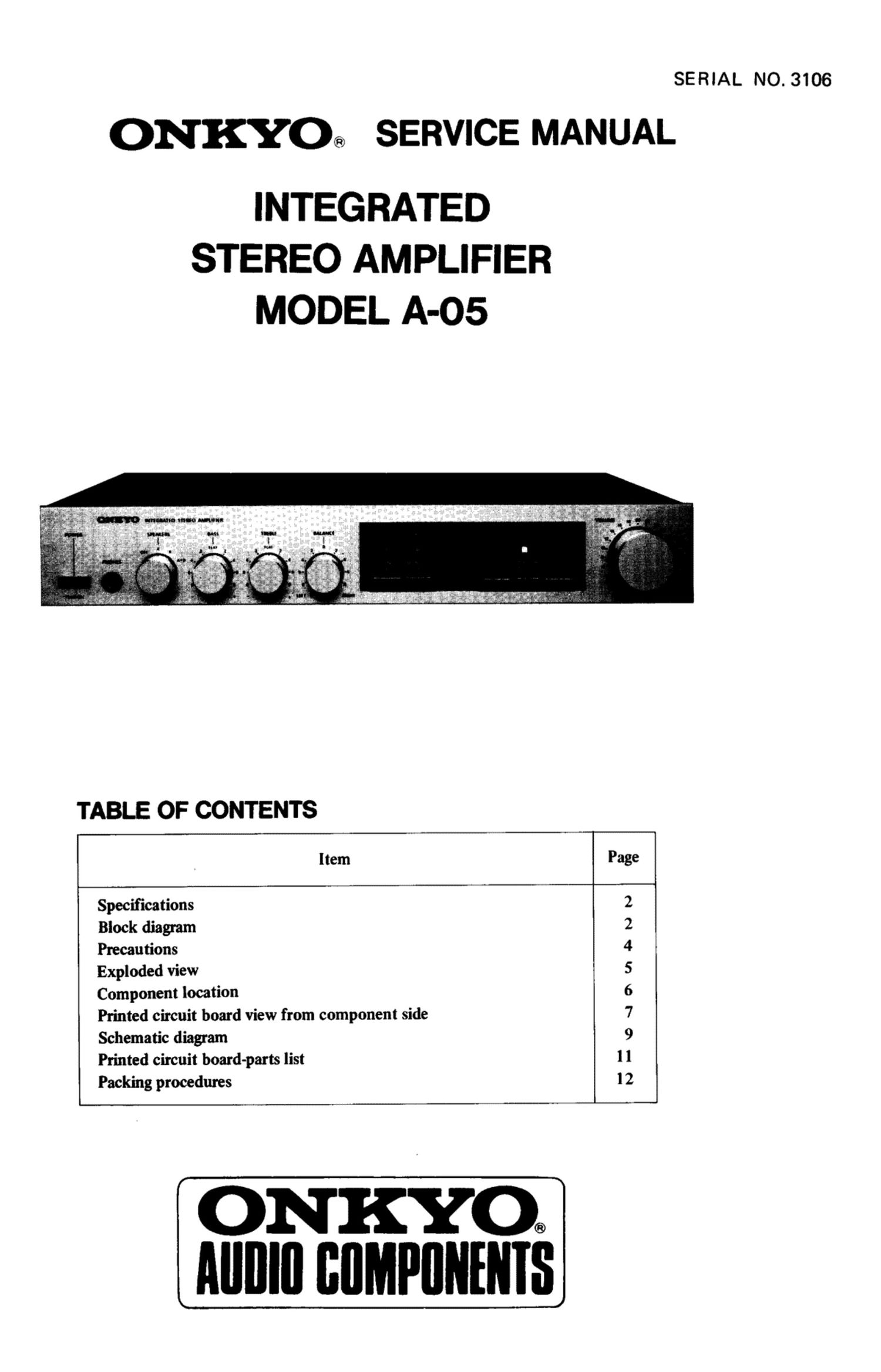
Onkyo A 05 Service Manual

This is the 8 pages manual for Onkyo A 05 Service Manual.
Read or download the pdf for free. If you want to contribute, please mail your pdfs to info@audioservicemanuals.com.

Page: 1 / 8
left right
Onkyo A 05 Service Manual

Extracted text from Onkyo A 05 Service Manual (Ocr-read)


Page 1

SERIAL NO. 3106

ONKYO® SERVICE MANUAL

INTEGRATED
STEREO AMPLIFIER
MODEL A-05

TABLE OF CONTENTS

'U
"3%

Item

Specifications

Block diagram

Precautions

Exploded view

Component location

Printed circuit board view from component side
Schematic diagram

Printed circuit board-parts list

Packing procedures

N-\O\IO\UI-§NN

H

NKYO
IIIIIIIII IIIIIIMPIIIIEII I5

Page 3

PRECAUTIONS

1. For continued protection against fire hazard, replace only with same type and same rating fuse.
CIRCUIT NO. PARTS NO. DESCRIPTION

F901 252047 2.5A (ST-6), AC fuse (D)

F901 252073 1.6A-SE-EAK, AC fuse (G/Q)
F911, F912 252077 4A-SE-EAK, AC fuse (G/Q)

F901 252025 25A-T, AC fuse (W)

F902 252073 1.6A-SE-EAK, AC fuse (W)

F501, F601 252006 3A (SS-2), Speaker protection fuse

2. Replacement for differential, driver, complementary and power amplifier transitors, if necessary, must be made from
the same beta (hFE) group as the original type.

3. Voltage Selector (rear panel)
Some models are equipped with a voltage selector to conform with local power supplies. Be sure to set this switch to match
the voltage of the power supply in your area before turning the power switch on. Voltage is changed by sliding the groove
in the switch with a screwdriver or similar instrument to the right or left position. Confirm that the switch has been moved
all the way to the right or left before turning the power switch on. If there is no voltage selector switch on the unit you
have purchased, it can only be used in areas where the power supply voltage is the same as that of the unit.

E R

220V ~ 120V~ 220V ~ 120V~
atAC 120V atACZQOV