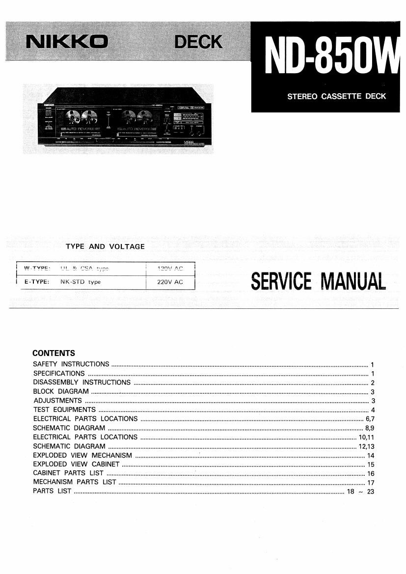
Nikko ND 850W tape sm

This is the 18 pages manual for Nikko ND 850W tape sm.
Read or download the pdf for free. If you want to contribute, please mail your pdfs to info@audioservicemanuals.com.

Page: 1 / 18
left right
Nikko ND 850W tape sm

Extracted text from Nikko ND 850W tape sm (Ocr-read)


Page 1

STEREO CASSETTE DECK

TYPE AND VOLTAGE

I 4
I!" TVDE- H5 2. (:KA mm; 1')n\/ [\f x

SERVICE MANUAL

CONTENTS

SAFETY INSTRUCTIONS
SPECIFICATIONS .............
DISASSEMBLY INSTRUCTIONS .
BLOCK DIAGRAM
ADJUSTMENTS
TEST EQUIPMENTS
ELECTRICAL PARTS LOCATIONS
SCHEMATIC DIAGRAM ................
ELECTRICAL PARTS LOCATIONS
SCHEMATIC DIAGRAM ................ 1213
EXPLODED VIEW MECHANISM
EXPLODED VIEW CABINET.
CABINET PARTS LIST ..........
MECHANISM PARTS LIST
PARTS LIST .............................

Page 2

I ND-850W

SAFETY INSTRUCTIONS

PRECAUTIONS DURING SERVICING

1.

Parts identified by the A symbol parts are critical for
safety. Replace only with same parts number specified.

Other parts and assemblies are specified for confor-
mance with such regulations as those applying to spuri-
ous radiation.

These must also be replaced only with specified replace-
ments.

Examples: RF converters, tuner units, RF cables, noise
blocking capacitors, noise blocking filters, etc.

Use specified internal wiring

a) Primary leads

b) Wires covered with PVC tubing
c) Double insulated wire

Use specified insulating materials for hazardous live
parts.

a) Insulation Tape

b) Insulated Barriers (Spacers)

c) PVC tubing

2 Plastic screw: ; ~

turnranlei

a) Terminal strips

SPECIFICATIONS

Heads:

Drive system:

Hard permalloy playback and
record-Z-gap ferrite erasing head x 1
Hard permalloy playback head x I
2-motor IC logic control

Motors: DC servo motor for capstan drive x 2
DC motor for reel drive x 2

Tape speed: 4.8 cm/sec.

Wow & flutter: 0.06% W.RMS (TA, TC, AY)

0.06% W.RMS i0.15% (DIN) (TE, TU)

Fast forward and

rewind time: Approx. 95 sec. (0-60 tape)

Frequency response: 30 - 18000 Hz with metal and

~20 dB input

30 - 16000 Hz with chrome position
tape and -20 dB input

30 - 15000 Hz with normal tape and
-20 dB input

When replacing the primary components (transformer,
power supply cord switch, by-pass capacitor, etc.),wrap
ends of wires securely about the terminals before sol-
dering.

Where hand soldering is involved, a minimum spacing
below between terminals of uninsulated live parts of pri-
mary or supply circuitry through air or over surface is to
be maintained.

120V appliance :3 mm spacing min.
220V and 240V appliance : 6 mm spacing min.

Observe that wires do not contact heat producing parts
(heatsinks, oxide metal resistance, rectifiers, etc.)

Check that replaced wires do not contact sharp edges or
pointed parts.

Do not leave electric conductive parts (screws, droplets,
etc.) inside the appliance.

SAFETY RECHECK AFTER SERVICING

Lontirm the specmee InSUIathn resrstance DCIVVESFI power
plug prongs and externally exposed parts of the appliance is
greater than 10Mohms, however, for equnpment wrth exter*
nal antenna terminals (tuner, receiver, etc) specified insula»
tion resistance should be more than 2.2Mohms (ground
terminals, in-output jacks etc).

Total distortion:
Bias frequency:
Input terminals:

Output terminals:

Maior dimensions:

Weight:

0.8% (400 Hz, 0 dB chrome position tape)
105 kHz

MIC: 0.7mV (6009 - 10km

LINE: 70mV (50kg)

LINE: 360mV (50kg)

Headphones: 0.1mW (8 ohm)
420(W)x115(H)x 270(D) mm

(including front panel knobs etc. and
rubber supports)

4.6 kg

Specifications are subject to change without notice.